Product Description
GPHQ F helical Parallel gearbox motor
GPHQ F helical parallel speed reduction gear box are based on the building block design,so it's convenient for them to fit all types of motors or connect with other power input.The same type of combine can fit motors with different power,so that it's possible for different types of machines to combine or connect.
GPHQ F series speed gear reducer is 1 kind of parallel shaft helical gear reducer , which consist of 2 or 3 stages helical
gears (relate to gear ratio) in the same case . The hard tooth surface gear use the high quality alloy steel ,the
process of carburizing and quenching, grinding 1,Output torque:200-18000(N.m)
1,Rated power:0.12-200(kw)
2,Input speed:≤3000 (rpm)
3,Output speed:≤393(rpm)
4,Transmission ratio:≥3.77
5,Series:2-3
6,Mounting way:M1-M6
GPHQ F helical reducer motor materials :
| housing material: | HT2OO high-strength cast iron for F37,47,57,67,77,87 HT250 High strength cast iron for F97,107,127,157 |
| Gear material: | 20CrMnTi |
| Housing hardness | HBS90-240 |
| Surface hardnesss of gear | HRC58°-62° |
| Gear core hardness | HRC33°-40° |
| Input/Output shaft material | 40Cr |
| Input/Output shaft hardness | HBS241°-286° |
| Shaft at oil seal postion hardness | HRC48 ° -55 ° |
| Machining precision of gears material | Accurate grinding 6-5 grade |
| Efficiency | up to 98% |
| Noise(Max) | 60-68dB |
| Tem.rise: | 40°C |
| Vibration | ≤20um |
| Motor | IP54, F class ,B5 FLANGE |
| color : | blue (if you need big quantity ,we can done as your wanted color ) |
Our reduction geared motor Advantage
1,reasonable price with excellent quality
2,delivery in time
3,safe ,reliable ,economical and durable
4,stable transmission ,quiet operation
5,smooth running and low noise
6,nice appearance ,durable service life
7,high heat-radiating efficiency ,high carrying ability
8,each gearbox must be tested before packing
9.reply in high efficiency during 1 working day
10. professional to produce gearbox and electric motor .
If there is any question, please don't hesitate to contact with me (EVA), U can send us your inquiry. And you will get response in 1 working day.
MOTOR CATALOGUE :
PRODUCING PROCESS:
WORKSHOP EQUIPMENT:
CERTIFICATION :
PACKAGE :
for 1 container, directly loading ,for less, all goods with pallet,
FAQ
1, Q:what's your MOQ for ac gearbox motor ?
A: 1pc is ok for each type electric gear box motor
2, Q: What about your warranty for your induction speed reducer motor ?
A: 1 year ,but except man-made destroyed
3, Q: which payment way you can accept ?
A: TT, western union .
4, Q: how about your payment way ?
A: 100%payment in advanced less $5000 ,30% payment in advanced payment , 70% payment before sending over $5000.
5, Q: how about your packing of speed reduction motor ?
A: plywood case ,if size is small ,we will pack with pallet for less 1 container
6, Q: What information should be given, if I buy electric helical geared motor from you ?
A: rated power, ratio or output speed,type ,voltage , mounting way , quantity , if more is better ,
/* January 22, 2571 19:08:37 */!function(){function s(e,r){var a,o={};try{e&&e.split(",").forEach(function(e,t){e&&(a=e.match(/(.*?):(.*)$/))&&1
| Application: | Motor, Machinery, Agricultural Machinery |
|---|---|
| Layout: | Bevel |
| Hardness: | Hardened Tooth Surface |
| Installation: | Horizontal Type |
| Step: | Double-Step |
| Type: | Bevel |
| Customization: |
Available
| Customized Request |
|---|

How do you install a bevel gear system?
Installing a bevel gear system involves several steps to ensure proper alignment, smooth operation, and efficient power transmission. Here's a detailed explanation of how to install a bevel gear system:
- Preparation: Before installing the bevel gear system, gather all the necessary tools and equipment. Ensure that you have the correct bevel gears, shafts, bearings, and any additional components required for your specific application. Familiarize yourself with the system's design, specifications, and installation instructions provided by the gear manufacturer.
- Clean and Inspect: Thoroughly clean all the components of the bevel gear system, including the gears, shafts, and bearings. Inspect them for any signs of damage, wear, or defects. Replace any damaged or worn-out parts to ensure optimal performance and longevity.
- Shaft Alignment: Proper alignment of the shafts is crucial for the bevel gear system's performance. Ensure that the shafts are aligned accurately, both angularly and axially, as specified by the manufacturer. Misalignment can lead to premature wear, increased noise, and reduced efficiency. Use precision measurement tools, such as dial indicators, to achieve the required alignment.
- Bearing Installation: Install the bearings on the shafts according to the manufacturer's instructions. Ensure that the bearings are securely fitted and properly lubricated. Proper bearing installation helps support the shafts, reduces friction, and ensures smooth rotation of the gears.
- Gear Meshing: Carefully position the bevel gears on the shafts, ensuring proper meshing between the teeth. The gear teeth should engage smoothly and evenly without any binding or excessive clearance. Achieving the correct gear meshing is crucial for efficient power transmission and to prevent premature wear or damage to the gears.
- Housing Assembly: Assemble the housing or casing that encloses the bevel gear system. Ensure that all housing components are aligned and securely fastened. Follow the manufacturer's instructions for proper housing assembly, including the use of gaskets or seals to prevent lubricant leakage and contamination.
- Lubrication: Proper lubrication is essential for the smooth operation and longevity of the bevel gear system. Apply the recommended lubricant to the gears, bearings, and other moving parts according to the manufacturer's specifications. Ensure that the lubricant used is compatible with the gear material, operating conditions, and environmental factors.
- Testing and Adjustment: After the installation is complete, perform a thorough system check. Rotate the shafts manually or using a suitable drive mechanism to ensure smooth gear operation, proper alignment, and absence of abnormal noise or vibration. Make any necessary adjustments, such as gear backlash or meshing depth, as per the manufacturer's guidelines and based on the specific application requirements.
It's important to note that the installation process may vary depending on the specific bevel gear system and application. Always refer to the manufacturer's instructions and guidelines for the particular gear system you are working with to ensure proper installation and optimal performance.
In summary, installing a bevel gear system involves preparation, cleaning and inspection, shaft alignment, bearing installation, gear meshing, housing assembly, lubrication, and thorough testing and adjustment. Following proper installation procedures and adhering to manufacturer guidelines are essential to achieve efficient power transmission, smooth operation, and the desired performance from the bevel gear system.

How do you retrofit an existing mechanical system with a bevel gear?
Retrofitting an existing mechanical system with a bevel gear involves modifying the system to incorporate the bevel gear for improved functionality or performance. Here's a detailed explanation of the retrofitting process:
- Evaluate the Existing System: Begin by thoroughly evaluating the existing mechanical system. Understand its design, components, and operational requirements. Identify the specific areas where the introduction of a bevel gear can enhance the system's performance, efficiency, or functionality.
- Analyze Compatibility: Assess the compatibility of the existing system with the integration of a bevel gear. Consider factors such as available space, load requirements, torque transmission, and alignment feasibility. Determine if any modifications or adaptations are necessary to accommodate the bevel gear.
- Design Considerations: Based on the system evaluation and compatibility analysis, develop a design plan for incorporating the bevel gear. Determine the appropriate gear type, size, and configuration that best suits the retrofitting requirements. Consider factors such as gear ratio, torque capacity, tooth profile, and mounting options.
- Modify Components: Identify the components that need modification or replacement to integrate the bevel gear. This may involve machining new shafts or shaft extensions, modifying housing or mounting brackets, or adapting existing components to ensure proper alignment and engagement with the bevel gear.
- Ensure Proper Alignment: Proper alignment is crucial for the successful integration of the bevel gear. Ensure that the existing system components and the bevel gear are aligned accurately to maintain smooth and efficient power transmission. This may involve adjusting shaft positions, aligning bearing supports, or employing alignment fixtures during the retrofitting process.
- Lubrication and Sealing: Consider the lubrication requirements of the bevel gear system. Ensure that appropriate lubricants are selected and provisions for lubrication are incorporated into the retrofit design. Additionally, pay attention to sealing arrangements to prevent lubricant leakage or ingress of contaminants into the gear system.
- Testing and Validation: After the retrofitting process is complete, conduct thorough testing and validation of the modified mechanical system. Ensure that the bevel gear functions as intended and meets the desired performance requirements. Perform functional tests, load tests, and monitor the system for any abnormalities or issues.
- Maintenance and Documentation: Develop a maintenance plan for the retrofitted system, including periodic inspection, lubrication, and any specific maintenance tasks related to the bevel gear. Document the retrofitting process, including design modifications, component specifications, alignment procedures, and any other relevant information. This documentation will be valuable for future reference, troubleshooting, or potential further modifications.
Retrofitting an existing mechanical system with a bevel gear requires careful planning, engineering expertise, and attention to detail. It is recommended to involve experienced gear engineers or professionals with expertise in retrofitting processes to ensure a successful integration and optimal performance of the bevel gear within the system.
By retrofitting an existing mechanical system with a bevel gear, it is possible to enhance its capabilities, improve efficiency, enable new functionalities, or address specific performance issues. Proper analysis, design, and implementation are essential to achieve a successful retrofit and realize the desired benefits of incorporating a bevel gear into the system.

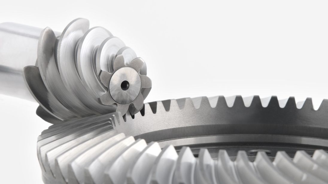
Can you explain the concept of straight and spiral bevel gears?
Straight and spiral bevel gears are two common types of bevel gears that have different tooth geometries and characteristics. Here's a detailed explanation of the concept of straight and spiral bevel gears:
Straight Bevel Gears:
Straight bevel gears are a type of bevel gears with straight-cut teeth that are machined on the cone-shaped surface of the gears. The teeth of straight bevel gears are parallel to the gear axis and intersect at a 90-degree angle. These gears are often used when the intersecting shafts need to transmit rotational motion at a right angle.
Straight bevel gears have the following characteristics:
- Tooth Engagement: In straight bevel gears, the tooth engagement occurs gradually as the gears rotate. This results in a relatively smooth and continuous transfer of power between the gears.
- Noise and Vibration: Straight bevel gears can produce more noise and vibration compared to other types of bevel gears, particularly at higher speeds. The straight-cut teeth create impact and noise during the engagement process.
- Efficiency: Straight bevel gears have relatively high efficiency due to their simple tooth geometry and direct engagement.
- Applications: Straight bevel gears are commonly used in applications such as automotive differentials, hand drills, and other mechanical power transmission systems where a 90-degree change in direction is required.
Spiral Bevel Gears:
Spiral bevel gears are another type of bevel gears with curved teeth that are machined on the cone-shaped surface of the gears. The teeth of spiral bevel gears are cut in a spiral pattern, gradually curving along the gear surface. This spiral tooth geometry provides several advantages over straight bevel gears.
Spiral bevel gears have the following characteristics:
- Tooth Engagement: Spiral bevel gears have a more gradual and smoother tooth engagement compared to straight bevel gears. The spiral-shaped teeth allow for progressive contact between the gears, resulting in reduced impact, noise, and vibration.
- Noise and Vibration: Spiral bevel gears produce less noise and vibration compared to straight bevel gears due to their improved tooth engagement characteristics.
- Load Capacity: Spiral bevel gears have higher load-carrying capacity compared to straight bevel gears due to the increased contact area between the gear teeth. This makes them suitable for applications that require higher torque transmission.
- Efficiency: Spiral bevel gears have slightly lower efficiency compared to straight bevel gears due to the sliding action between the teeth during engagement. However, advancements in gear design and manufacturing techniques have improved their efficiency.
- Applications: Spiral bevel gears are commonly used in applications where smooth and quiet operation is required, such as automotive rear axle drives, machine tools, and industrial machinery.
In summary, straight bevel gears have straight-cut teeth that intersect at a 90-degree angle, while spiral bevel gears have curved teeth that engage in a spiral pattern. Straight bevel gears are suitable for applications that require a right angle change in direction, while spiral bevel gears provide smoother engagement, reduced noise, and higher load-carrying capacity. The selection between straight and spiral bevel gears depends on the specific requirements of the application, including the desired level of noise, vibration, efficiency, and torque transmission.


editor by Dream 2024-05-09
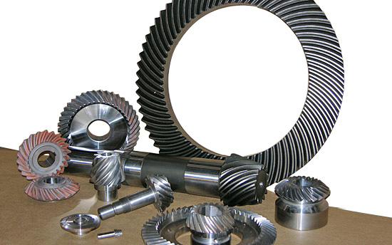
China Standard Customize Different Models of Stainless Steel Bevel Gears and Worm Gears gear ratio calculator
Product Description
1) According to the different strength and performance, we choose the steel with strong compression;
2) Using Germany professional software and our professional engineers to design products with more reasonable size and better performance; 3) We can customize our products according to the needs of our customers,Therefore, the optimal performance of the gear can be exerted under different working conditions;
4) Quality assurance in every step to ensure product quality is controllable.
Product Paramenters
| DRIVEN GEAR |
NUMBER OF TEETH |
12 |
|
MODULE |
4.5 | |
|
LENTH |
372 | |
|
OUTER DIAMETER |
ø60 |
|
|
DIRECTION OF SPIRAL |
R |
|
|
ACCURACY OF SPLINE |
M27*1.5-6g | |
|
NUMBER OF SPLINE |
13/18 |
|
DRIVEN GEAR |
NUMBER OF TEETH |
56 |
|
OUTER DIAMETER |
ø251 |
|
|
DIAMETER OF INNER HOLE |
ø149 |
|
|
ACCURACY OF SCREW |
10-M10*1.25-6H | |
|
CENTER DISTANCE OF SCREW HOLE |
ø177 |
|
|
DIRECTION OF SPIRAL |
L |
Company Profiles
Our company,HangZhou CHINAMFG Gear co.,Ltd , specialized in Hypoid and spiral bevel gear used in Automotive industry, was foundeded in 1996, with registered capital 136,8 square meter, with building area of 72,000 square meters. More than 500 employees work in our company.
We own more than 560 high-precise machining equipments, 10 Klingelnberg Oerlikon gear production lines, 36 Gleason gear production lines, 5 forging production lines 2 german Aichilin and 5 CHINAMFG CHINAMFG advanced automatic continuous heat treatment production lines. With the introducing the advanced Oerlikon C50 and P65 measuring center, we enhence our technology level and improve our product quality a lot. We offer better quality and good after-sale service with low price, which insure the good reputation. With the concept of "for the people, by technology, creativity, for the society, transfering friendship, honest", we are trying to provice the world-top level product.
Our aim is: CHINAMFG Gear,world class, Drive the world.
According to the different strength and performance, we choose the steel with strong compression;Using Germany professional software and our professional engineers to design products with more reasonable size and better performance;We can customize our products according to the needs of our customers,Therefore, the optimal performance of the gear can be exerted under different working conditions;Quality assurance in every step to ensure product quality is controllable.
Our company had full quality management system and had been certified by ISO9001:2000, QS-9000:1998, ISO/TS16949 , which insure the entrance of international market.
Certification & honors
Packaging & Shipping
Packaging Detail:standard package(carton ,wooden pallet).
Shipping:Support Sea freight. Accept FOB,EXW,FAS,DES.
Cooperative customers
HangZhou CHINAMFG Gear Co., Ltd. adheres to the concept of "people-oriented, prosper with science and technology; create high-quality products, contribute to the society; turn friendship, and contribute sincerely", and will strive to create world automotive axle spiral bevel gear products.
1.Do you provide samples?
Yes,we can offer free sample but not pay the cost of freight.
2.What about OEM?
Yes,we can do OEM according to your requirements.
3.How about after-sales service?
We have excellent after-sales service if you have any quanlity problem,you can contact us anytime.
4.What about package?
Stardard package or customized package as requirements.
5.How to ensure the quanlity of the products?
We can provide raw meterial report,metallographic examination and the accuracy testing etc.
6.How long is your delivery time?
Genarally it is 4-7 days.If customized it will be take 20 days according to your quantity. /* January 22, 2571 19:08:37 */!function(){function s(e,r){var a,o={};try{e&&e.split(",").forEach(function(e,t){e&&(a=e.match(/(.*?):(.*)$/))&&1
| Application: | Motor, Electric Cars, Motorcycle, Machinery, Marine, Agricultural Machinery, Car |
|---|---|
| Hardness: | Hardened Tooth Surface |
| Gear Position: | External Gear |
| Manufacturing Method: | Cast Gear |
| Toothed Portion Shape: | Herringbone Gear |
| Material: | Cast Steel |
| Samples: |
US$ 60/Set
1 Set(Min.Order) | |
|---|
| Customization: |
Available
| Customized Request |
|---|
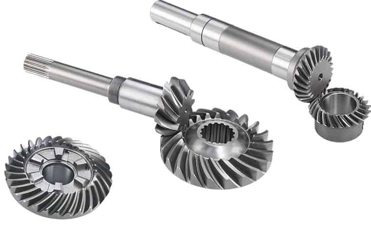
Can you provide examples of machinery that use bevel gears?
Bevel gears are widely used in various machinery and mechanical systems where torque transmission and direction changes are required. These gears are specifically designed to transmit power between intersecting shafts at different angles. Here are some examples of machinery and equipment that commonly use bevel gears:
- Automotive Industry: Bevel gears are extensively used in automotive applications. They can be found in different parts of vehicles, including the differential gear system, powertrain components, steering systems, and transfer cases. In the differential, bevel gears help distribute torque between the drive wheels while allowing them to rotate at different speeds during turns.
- Aerospace Industry: Bevel gears are utilized in various aerospace applications, such as aircraft engines, landing gear systems, and helicopter transmissions. They play a critical role in transferring power and changing the direction of rotation in these high-performance systems.
- Industrial Machinery: Bevel gears are commonly employed in industrial machinery and equipment. They are used in gearboxes, speed reducers, and power transmission systems. Examples include conveyors, mixers, pumps, packaging machinery, printing presses, and textile machinery. Bevel gears allow efficient power transmission and enable the machinery to operate at different speeds and directions as required by the specific application.
- Construction and Heavy Equipment: Bevel gears are found in construction equipment such as cranes, excavators, loaders, and bulldozers. They are integral components of the drivetrain systems, enabling the transfer of power and torque to the wheels or tracks, as well as facilitating steering and movement of the equipment.
- Marine Applications: Bevel gears are utilized in various marine applications, including propulsion systems, marine generators, winches, steering mechanisms, and anchor handling equipment. They help transmit power efficiently and withstand the challenging marine environment.
- Machine Tools: Bevel gears are employed in machine tools such as milling machines, lathes, and grinders. They are essential for transmitting power and facilitating the required speed and direction changes in these precision machining systems.
- Power Plants: Bevel gears are used in power generation facilities, including wind turbines, hydroelectric turbines, and steam turbines. They play a crucial role in converting the rotational motion of the turbine blades into electrical energy by transmitting torque to the generator.
- Mining and Material Handling: Bevel gears are commonly found in mining equipment, conveyor systems, and material handling machinery. They are used to transfer power and facilitate the movement of bulk materials, such as ores, coal, and aggregates.
These examples represent just a few of the many applications where bevel gears are utilized. Bevel gears offer versatility, efficiency, and reliability in transmitting power and changing direction in various mechanical systems across different industries.

What are the environmental considerations when using bevel gears?
When using bevel gears, there are several environmental considerations to keep in mind. These considerations encompass aspects such as material selection, lubrication, noise generation, and waste management. Here's a detailed explanation:
1. Material Selection: The choice of materials for bevel gears can have environmental implications. Opting for environmentally friendly materials, such as recyclable or biodegradable materials, can help reduce the environmental impact. Additionally, selecting materials with low toxicity or hazardous properties contributes to safer handling and disposal practices.
2. Lubrication: Proper lubrication is essential for the efficient operation of bevel gears. However, the choice and use of lubricants can have environmental consequences. It is advisable to select lubricants that are environmentally friendly, such as biodegradable or non-toxic lubricants, to minimize the risk of contamination in case of leaks or spills. Additionally, implementing effective lubricant management practices, such as proper containment and recycling, helps reduce environmental pollution.
3. Noise Generation: Bevel gears can generate noise during operation, which can have environmental implications, especially in noise-sensitive areas or workplaces. Excessive noise can contribute to noise pollution and affect the well-being of individuals in the vicinity. Implementing noise reduction measures, such as using noise-dampening materials, optimizing gear design for quieter operation, and implementing proper maintenance practices, can help minimize noise pollution.
4. Energy Efficiency: Bevel gears are part of power transmission systems that consume energy. Considering energy efficiency in gear system design and operation can contribute to reduced energy consumption and lower environmental impact. This can be achieved by optimizing gear designs for higher efficiency, reducing friction losses through proper lubrication and surface treatments, and implementing efficient power transmission systems.
5. Waste Management: The manufacturing and maintenance processes involving bevel gears can generate waste materials, such as metal shavings, lubricant residues, or worn-out gears. Proper waste management practices, including recycling and disposal, are crucial to minimize the environmental impact. Recycling materials whenever possible and ensuring the proper disposal of hazardous or toxic waste materials are important considerations in reducing environmental pollution.
6. Life Cycle Assessment: Conducting a life cycle assessment (LCA) of bevel gears can provide a comprehensive understanding of their environmental impact. LCA takes into account the environmental implications associated with the entire life cycle of the gears, including raw material extraction, manufacturing, use, and end-of-life disposal. This assessment helps identify areas for improvement and guides decision-making towards more sustainable practices.
By considering these environmental factors, manufacturers, engineers, and users of bevel gears can make conscious choices to minimize the environmental impact associated with their production, operation, and disposal. Implementing sustainable practices and adhering to environmental regulations and standards contribute to a greener and more sustainable use of bevel gears.
How do you choose the right size bevel gear for your application?
Choosing the right size bevel gear for your application involves considering various factors such as load requirements, speed ratios, tooth geometry, and material selection. Here's a detailed explanation of the considerations involved in selecting the right size bevel gear:
- Load Requirements: Determine the torque and power requirements of your application. This involves understanding the load conditions, including the magnitude and direction of the applied forces. Calculate the required torque capacity of the bevel gear based on the expected load and operating conditions.
- Speed Ratios: Determine the desired speed ratios between the input and output shafts. Bevel gears are often used to transmit rotational motion at different speeds. Calculate the required gear ratio to achieve the desired speed output and select bevel gears with appropriate tooth counts to achieve the desired ratio.
- Tooth Geometry: Consider the tooth geometry of the bevel gears. Straight bevel gears and spiral bevel gears have different tooth profiles and engagement characteristics. Evaluate the impact of tooth geometry on factors such as noise, vibration, smoothness of operation, and load-carrying capacity. Choose the tooth profile that best suits the specific requirements of your application.
- Material Selection: Consider the material properties of the bevel gears. The material should have sufficient strength, durability, and resistance to wear and fatigue. Common materials for bevel gears include steel alloys, cast iron, and non-ferrous alloys. The material selection should be based on factors such as load requirements, operating conditions (e.g., temperature, moisture), and any specific industry standards or regulations.
- Size and Dimensions: Consider the physical size and dimensions of the bevel gears. Evaluate the available space and clearance in your application to ensure proper fit and alignment of the gears. Consider factors such as the gear diameter, face width, and shaft bore diameter. Ensure that the selected bevel gears can be mounted and meshed correctly with the mating gears.
- Manufacturing and Cost Considerations: Take into account any specific manufacturing considerations or constraints. Consider factors such as gear manufacturing methods (e.g., cutting, shaping, forging), availability of standard gear sizes or custom gear manufacturing options, and associated costs. Balance the performance requirements of your application with the available budget and manufacturing feasibility.
It is often beneficial to consult with gear manufacturers, engineers, or industry experts to ensure the proper selection of bevel gears for your specific application. They can provide guidance on gear design, material selection, and performance analysis to help you choose the right size bevel gear that meets your requirements.
In summary, choosing the right size bevel gear involves considering factors such as load requirements, speed ratios, tooth geometry, material selection, size and dimensions, and manufacturing considerations. Taking into account these factors will help ensure that the selected bevel gear is suitable for your application, providing reliable and efficient power transmission.
editor by Dream 2024-05-08
China supplier Customized CNC Machined POM spiral Bevel Gear wholesaler
Product Description
Our Services
Product Design Material Selection
Mold Design Mold Making
Bulk Production Logo Printing
Surface Treatment Assembling
Packaging Door to Door Delivery
| Material | Nylon ,mc nylon, POM,ABS,PU,PP,PE,PTFE,UHMWPE,HDPE,LDPE, PVC,etc. |
| Color | Black, white, red, green, transparent or any color according to Pantone code |
| Size | As per customer's requirements |
| Technology | Injection molding, CNC machining, Extrusion |
| Surface Treatment | Powder coating, Zinc coating, Galvanization, Electro-deposition coating, Chrome/zinc/nickel plating, Polishing, Silkscreen, Black oxide |
| Application | Automotive, ATV, Mechanical equipment, Construction, Home appliance, Aviation, Office facilities, Agriculture, etc. |
| Shippment | We have longterm cooperation with internation shipping agent and express company, so that shipping safty and arriving time are secured |
Detail Image
Why Choose Us
Our Machine
Product Range
Contact Us /* January 22, 2571 19:08:37 */!function(){function s(e,r){var a,o={};try{e&&e.split(",").forEach(function(e,t){e&&(a=e.match(/(.*?):(.*)$/))&&1
| Application: | Motor, Electric Cars, Machinery, Toy, Car |
|---|---|
| Hardness: | Hardened Tooth Surface |
| Gear Position: | External Gear |
| Manufacturing Method: | Cast Gear |
| Toothed Portion Shape: | Spur Gear |
| Material: | Plastic |
| Samples: |
US$ 0/Piece
1 Piece(Min.Order) | |
|---|
| Customization: |
Available
| Customized Request |
|---|
Are bevel gears suitable for high-torque applications?
Bevel gears can indeed be suitable for high-torque applications, depending on various factors such as the specific design, material selection, and proper application engineering. Here's a detailed explanation:
Bevel gears are known for their ability to transmit power between intersecting shafts at different angles. They can handle significant torque loads and are commonly used in applications that require high-torque transmission. However, the suitability of bevel gears for high-torque applications depends on the following factors:
- Design: The design of the bevel gears plays a crucial role in their ability to handle high torque. Factors such as tooth profile, size, and geometry impact the load-carrying capacity and torque transmission capability. Bevel gears with robust and optimized designs, including suitable tooth profiles and adequate tooth engagement, can effectively handle high-torque applications.
- Material Selection: The choice of materials for bevel gears is critical in high-torque applications. Gears need to be made from materials with high strength, hardness, and wear resistance to withstand the forces and stresses involved in transmitting high torque. Common materials used for bevel gears include alloy steels, carburizing steels, and specialty alloys. Material selection should consider the specific torque requirements, operating conditions, and anticipated loads to ensure the gears can handle the desired torque levels.
- Lubrication: Proper lubrication is essential for reducing friction, wear, and heat generation in high-torque bevel gear applications. Adequate lubrication helps maintain a lubricating film between the gear teeth, minimizing metal-to-metal contact and associated losses. The lubricant type, viscosity, and replenishment schedule should be selected based on the torque and operating conditions to ensure effective lubrication and minimize gear wear.
- Gear Size and Ratio: The size of the bevel gears and the gear ratio can influence their torque-handling capability. Larger gears generally have greater tooth strength and load-carrying capacity, making them more suitable for high-torque applications. The gear ratio should also be considered to ensure it is appropriate for the desired torque transmission and to avoid excessive loads on the gears.
- Operating Conditions: The operating conditions, including speed, temperature, and shock loads, must be taken into account when determining the suitability of bevel gears for high-torque applications. Higher speeds and extreme operating temperatures can affect the gear material properties, lubrication performance, and overall gear system efficiency. Proper cooling, temperature control, and gear protection measures should be implemented to maintain reliable performance under high-torque conditions.
By considering these factors and properly engineering the bevel gear system, it is possible to utilize bevel gears in high-torque applications effectively. However, it is crucial to consult with experienced engineers and perform thorough analysis and testing to ensure the gears can handle the specific torque requirements of the application.
How do you address noise and vibration issues in a bevel gear system?
Noise and vibration issues in a bevel gear system can be disruptive, affect performance, and indicate potential problems. Addressing these issues involves identifying the root causes and implementing appropriate solutions. Here's a detailed explanation:
When dealing with noise and vibration in a bevel gear system, the following steps can help address the issues:
- Analyze the System: Begin by analyzing the system to identify the specific sources of noise and vibration. This may involve conducting inspections, measurements, and tests to pinpoint the areas and components contributing to the problem. Common sources of noise and vibration in a bevel gear system include gear misalignment, improper meshing, inadequate lubrication, worn gears, and resonance effects.
- Check Gear Alignment: Proper gear alignment is crucial for minimizing noise and vibration. Misalignment can cause uneven loading, excessive wear, and increased noise. Ensure that the bevel gears are correctly aligned both axially and radially. This can involve adjusting the mounting position, shimming, or realigning the gears to achieve the specified alignment tolerances.
- Optimize Gear Meshing: Proper gear meshing is essential for reducing noise and vibration. Ensure that the gear teeth profiles, sizes, and surface qualities are suitable for the application. Improper tooth contact, such as excessive or insufficient contact, can lead to noise and vibration issues. Adjusting the gear tooth contact pattern, modifying gear profiles, or using anti-backlash gears can help optimize gear meshing and reduce noise and vibration.
- Ensure Adequate Lubrication: Proper lubrication is critical for minimizing friction, wear, and noise in a bevel gear system. Insufficient lubrication or using the wrong lubricant can lead to increased friction and noise generation. Check the lubrication system, ensure the correct lubricant type and viscosity are used, and verify that the gears are adequately lubricated. Regular lubricant analysis and maintenance can help maintain optimal lubrication conditions and reduce noise and vibration.
- Inspect and Replace Worn Gears: Worn or damaged gears can contribute to noise and vibration problems. Regularly inspect the gears for signs of wear, pitting, or tooth damage. If significant wear is detected, consider replacing the worn gears with new ones to restore proper gear meshing and reduce noise. Additionally, ensure that the gear materials are suitable for the application and provide adequate strength and durability.
- Address Resonance Effects: Resonance can amplify noise and vibration in a bevel gear system. Identify any resonant frequencies within the system and take steps to mitigate their effects. This may involve adjusting gear parameters, adding damping materials or structures, or altering the system's natural frequencies to minimize resonance and associated noise and vibration.
Implementing these steps can help address noise and vibration issues in a bevel gear system. However, it is important to note that each system is unique, and the specific solutions may vary depending on the circumstances. Consulting with experts in gear design and vibration analysis can provide valuable insights and ensure effective resolution of noise and vibration problems.

How do you calculate the gear ratio of a bevel gear?
Calculating the gear ratio of a bevel gear involves determining the ratio between the number of teeth on the driving gear (pinion) and the driven gear (crown gear). Here's a detailed explanation of how to calculate the gear ratio of a bevel gear:
The gear ratio is determined by the relationship between the number of teeth on the pinion and the crown gear. The gear ratio is defined as the ratio of the number of teeth on the driven gear (crown gear) to the number of teeth on the driving gear (pinion). It can be calculated using the following formula:
Gear Ratio = Number of Teeth on Crown Gear / Number of Teeth on Pinion Gear
For example, let's consider a bevel gear system with a crown gear that has 40 teeth and a pinion gear with 10 teeth. The gear ratio can be calculated as follows:
Gear Ratio = 40 / 10 = 4
In this example, the gear ratio is 4:1, which means that for every four revolutions of the driving gear (pinion), the driven gear (crown gear) completes one revolution.
It's important to note that the gear ratio can also be expressed as a decimal or a percentage. For the example above, the gear ratio can be expressed as 4 or 400%.
Calculating the gear ratio is essential for understanding the speed relationship and torque transmission between the driving and driven gears in a bevel gear system. The gear ratio determines the relative rotational speed and torque amplification or reduction between the gears.
It's worth mentioning that the gear ratio calculation assumes ideal geometries and does not consider factors such as backlash, efficiency losses, or any other system-specific considerations. In practical applications, it's advisable to consider these factors and consult gear manufacturers or engineers for more accurate calculations and gear selection.
In summary, the gear ratio of a bevel gear is determined by dividing the number of teeth on the crown gear by the number of teeth on the pinion gear. The gear ratio defines the speed and torque relationship between the driving and driven gears in a bevel gear system.
editor by Dream 2024-05-08
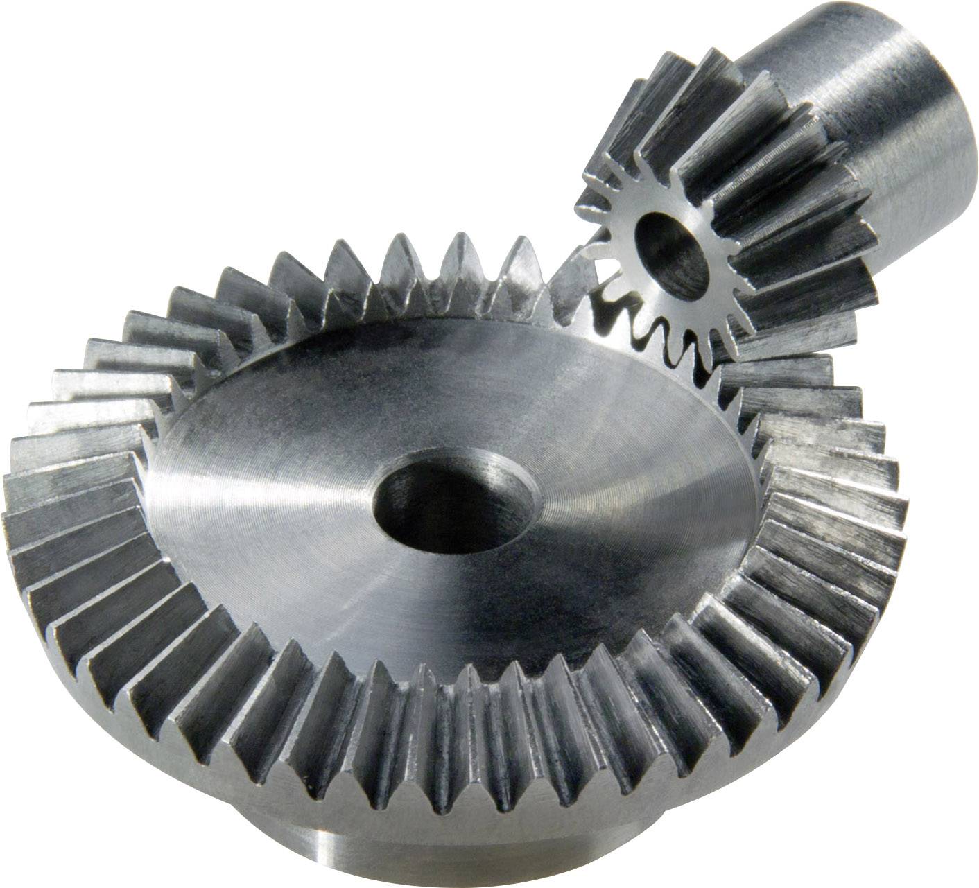
China Standard ANSI Standard Bevel Gear M2.5 helical bevel gear
Product Description
XIHU (WEST LAKE) DIS.HUA Chain Group is the most professional manufacturer of power transmission in China, manufacturing roller chains, industry sprockets, motorcycle sprockets, casting sprockets, different type of couplings, pulleys, taper bushes, locking devices, gears, shafts, CNC precision parts and so on.
We adopt good quality raw material and strict with DIN, ANSI, JIS standard ect, We have professional quality conrol team, complet equipment, advanaced technology. In 1999, Xihu (West Lake) Dis.hua obtained ISO9001 Certificate of Quality Assurance System, besides, the company also devotes itselt o environmental protection, In2002, it also obtained ISO14001 Certificate of Environment Management System.
Standard bevel gear with spline
Gear with straight teeth
Precision Forging
Mould from 0.5--16
20CrMnTi, 20Cr, 40Cr
Carburization
High quality lubrication
| Spiral Bevel Gear | Gear | Spline I | Spline II | |
| Module | Min | 1.5 | 1.5 | - |
| Max | 5.0 | 4.0 | - | |
| Teeth Number | Min | 16 | 30 | - |
| Max | 30 | 50 | - | |
| Pressure Angle | Min | 17° | 20° | - |
| Max | 25° | 30° | - | |
| Pitch Angle | Min | 18° | - | - |
| Max | 56° | - | - | |
| Spiral Angle | Min | 20° | - | - |
| Max | 35° | - | - | |
| O.D | Min | 26 | - | - |
| Max | 157 | - | - | |
| L(max) | 200 | |||
/* January 22, 2571 19:08:37 */!function(){function s(e,r){var a,o={};try{e&&e.split(",").forEach(function(e,t){e&&(a=e.match(/(.*?):(.*)$/))&&1
| Application: | Industry |
|---|---|
| Hardness: | Hardened |
| Gear Position: | External Gear |
| Manufacturing Method: | Rolling Gear |
| Toothed Portion Shape: | Bevel Wheel |
| Material: | Cast Iron |
| Customization: |
Available
| Customized Request |
|---|
How do you install a bevel gear system?
Installing a bevel gear system involves several steps to ensure proper alignment, smooth operation, and efficient power transmission. Here's a detailed explanation of how to install a bevel gear system:
- Preparation: Before installing the bevel gear system, gather all the necessary tools and equipment. Ensure that you have the correct bevel gears, shafts, bearings, and any additional components required for your specific application. Familiarize yourself with the system's design, specifications, and installation instructions provided by the gear manufacturer.
- Clean and Inspect: Thoroughly clean all the components of the bevel gear system, including the gears, shafts, and bearings. Inspect them for any signs of damage, wear, or defects. Replace any damaged or worn-out parts to ensure optimal performance and longevity.
- Shaft Alignment: Proper alignment of the shafts is crucial for the bevel gear system's performance. Ensure that the shafts are aligned accurately, both angularly and axially, as specified by the manufacturer. Misalignment can lead to premature wear, increased noise, and reduced efficiency. Use precision measurement tools, such as dial indicators, to achieve the required alignment.
- Bearing Installation: Install the bearings on the shafts according to the manufacturer's instructions. Ensure that the bearings are securely fitted and properly lubricated. Proper bearing installation helps support the shafts, reduces friction, and ensures smooth rotation of the gears.
- Gear Meshing: Carefully position the bevel gears on the shafts, ensuring proper meshing between the teeth. The gear teeth should engage smoothly and evenly without any binding or excessive clearance. Achieving the correct gear meshing is crucial for efficient power transmission and to prevent premature wear or damage to the gears.
- Housing Assembly: Assemble the housing or casing that encloses the bevel gear system. Ensure that all housing components are aligned and securely fastened. Follow the manufacturer's instructions for proper housing assembly, including the use of gaskets or seals to prevent lubricant leakage and contamination.
- Lubrication: Proper lubrication is essential for the smooth operation and longevity of the bevel gear system. Apply the recommended lubricant to the gears, bearings, and other moving parts according to the manufacturer's specifications. Ensure that the lubricant used is compatible with the gear material, operating conditions, and environmental factors.
- Testing and Adjustment: After the installation is complete, perform a thorough system check. Rotate the shafts manually or using a suitable drive mechanism to ensure smooth gear operation, proper alignment, and absence of abnormal noise or vibration. Make any necessary adjustments, such as gear backlash or meshing depth, as per the manufacturer's guidelines and based on the specific application requirements.
It's important to note that the installation process may vary depending on the specific bevel gear system and application. Always refer to the manufacturer's instructions and guidelines for the particular gear system you are working with to ensure proper installation and optimal performance.
In summary, installing a bevel gear system involves preparation, cleaning and inspection, shaft alignment, bearing installation, gear meshing, housing assembly, lubrication, and thorough testing and adjustment. Following proper installation procedures and adhering to manufacturer guidelines are essential to achieve efficient power transmission, smooth operation, and the desired performance from the bevel gear system.
How do you retrofit an existing mechanical system with a bevel gear?
Retrofitting an existing mechanical system with a bevel gear involves modifying the system to incorporate the bevel gear for improved functionality or performance. Here's a detailed explanation of the retrofitting process:
- Evaluate the Existing System: Begin by thoroughly evaluating the existing mechanical system. Understand its design, components, and operational requirements. Identify the specific areas where the introduction of a bevel gear can enhance the system's performance, efficiency, or functionality.
- Analyze Compatibility: Assess the compatibility of the existing system with the integration of a bevel gear. Consider factors such as available space, load requirements, torque transmission, and alignment feasibility. Determine if any modifications or adaptations are necessary to accommodate the bevel gear.
- Design Considerations: Based on the system evaluation and compatibility analysis, develop a design plan for incorporating the bevel gear. Determine the appropriate gear type, size, and configuration that best suits the retrofitting requirements. Consider factors such as gear ratio, torque capacity, tooth profile, and mounting options.
- Modify Components: Identify the components that need modification or replacement to integrate the bevel gear. This may involve machining new shafts or shaft extensions, modifying housing or mounting brackets, or adapting existing components to ensure proper alignment and engagement with the bevel gear.
- Ensure Proper Alignment: Proper alignment is crucial for the successful integration of the bevel gear. Ensure that the existing system components and the bevel gear are aligned accurately to maintain smooth and efficient power transmission. This may involve adjusting shaft positions, aligning bearing supports, or employing alignment fixtures during the retrofitting process.
- Lubrication and Sealing: Consider the lubrication requirements of the bevel gear system. Ensure that appropriate lubricants are selected and provisions for lubrication are incorporated into the retrofit design. Additionally, pay attention to sealing arrangements to prevent lubricant leakage or ingress of contaminants into the gear system.
- Testing and Validation: After the retrofitting process is complete, conduct thorough testing and validation of the modified mechanical system. Ensure that the bevel gear functions as intended and meets the desired performance requirements. Perform functional tests, load tests, and monitor the system for any abnormalities or issues.
- Maintenance and Documentation: Develop a maintenance plan for the retrofitted system, including periodic inspection, lubrication, and any specific maintenance tasks related to the bevel gear. Document the retrofitting process, including design modifications, component specifications, alignment procedures, and any other relevant information. This documentation will be valuable for future reference, troubleshooting, or potential further modifications.
Retrofitting an existing mechanical system with a bevel gear requires careful planning, engineering expertise, and attention to detail. It is recommended to involve experienced gear engineers or professionals with expertise in retrofitting processes to ensure a successful integration and optimal performance of the bevel gear within the system.
By retrofitting an existing mechanical system with a bevel gear, it is possible to enhance its capabilities, improve efficiency, enable new functionalities, or address specific performance issues. Proper analysis, design, and implementation are essential to achieve a successful retrofit and realize the desired benefits of incorporating a bevel gear into the system.

What are the benefits of using a bevel gear mechanism?
Using a bevel gear mechanism offers several benefits in various applications. Here's a detailed explanation of the advantages of using a bevel gear mechanism:
- Change in Direction: Bevel gears are designed to transmit rotational motion between intersecting or non-parallel shafts. They enable a change in direction of motion, allowing the rotary power to be transmitted efficiently at different angles, such as 90 degrees or more. This capability is particularly useful in applications where space constraints or specific mechanical arrangements require a change in direction.
- Speed Reduction or Increase: Bevel gears can be used to achieve speed reduction or increase between the input and output shafts. By selecting bevel gears with different tooth counts, the rotational speed can be adjusted according to the desired output requirements. This feature is beneficial in applications where different speeds are needed for specific operations or to match the requirements of the driven equipment.
- Compact Design: Bevel gears offer a compact design that allows for efficient power transmission in applications with limited space. The intersecting shafts and compact arrangement of the gear teeth enable the transmission of torque and motion in a more confined area compared to other types of gear mechanisms.
- High Torque Transmission: Bevel gears are capable of transmitting high torque loads. The meshing of the gear teeth provides a strong and reliable connection, allowing for the efficient transfer of power even in heavy-duty applications. This makes bevel gears suitable for applications that require the transmission of substantial torque, such as in automotive differentials, industrial machinery, and mining equipment.
- Versatility: Bevel gears are versatile and can be designed to accommodate various operating conditions and requirements. They can be manufactured with different tooth profiles, such as straight-cut, spiral, or zerol, to optimize performance based on factors like noise reduction, load capacity, and efficiency. Additionally, bevel gears can be made from different materials, allowing them to withstand different environmental conditions and requirements.
- Smooth and Quiet Operation: The tooth geometry of spiral bevel gears provides smoother and quieter operation compared to straight-cut gears. The gradual engagement of the curved teeth reduces noise, vibration, and shock during gear meshing, resulting in quieter operation and improved overall system performance. This makes bevel gears suitable for applications where noise reduction is a critical consideration.
- Wide Range of Applications: Bevel gears find applications in various industries and systems where changes in direction, speed, and torque transmission are required. They are used in automotive differentials, marine propulsion systems, industrial machinery, robotics, aerospace systems, and more. The versatility and adaptability of bevel gears make them suitable for a wide range of applications across different sectors.
In summary, using a bevel gear mechanism provides benefits such as change in direction, speed adjustment, compact design, high torque transmission, versatility, smooth and quiet operation, and suitability for a wide range of applications. These advantages make bevel gears a preferred choice in numerous industries and systems that require efficient and reliable power transmission.
editor by Dream 2024-05-07
China Professional China Worm Gear Box Gearbox Helical Bevel Gear Manufacturer helical bevel gear
Product Description
Product Description
| Material: | 45#Steel,20CrMnTi,40Cr,20CrNiMo,20MnCr5,GCR15SiMn,42CrMo,2Cr13stainless steel,Nylon,Bakelite,Copper,Aluminium.etc |
| Process: | The main process is Gear Hobbing, Gear Shaping and Gear Grinding, Selecting production process according to the different products. |
| Heat Treatmente: | Carburizing and quenching ,High-frequency quenching,Nitriding, Hardening and tempering, Selecting heat treatment according to the different materials. |
| Testing Equipment | Rockwell hardness tester 500RA,
Double mesh instrument HD-200B & 3102, Gear measurement center instrument CNC3906T other High precision detection equipments |
| Certification | 0.1-90 kg |
| Casting Size: | Max linear size: 1200 mm, Max diameter size: 600 mm |
| Machining tolerace: | GB/T19001-2016/ISO9001:2015 |
| Machining surface roughness: | Ra0.8 ~ 6.3 um |
| Material standard: | GB, ASTM, AISI, DIN, BS, JIS, NF, AS, AAR |
| Usage: | Used in printing machine, cleaning machine, medical equipment, garden machine, construction machine, electric car, valve, forklift, transportation equipment and various gear reducers.etc |
| Quality control: | 100% inspection before packing |
| Manufacture Standard | 5-8 Grade ISO1328-1997. |
Company Profile
SIMIS CASTING, established in year of 2004, is a professional foundry, including integrating development and production together, specialized in producing various kinds of investment casting parts, and CHINAMFG parts. These casting parts are widely used in automobile industry, railway vehicle, construction machine, municipal works, pipeline, petrochemical industry, mine, electric utility industry and so on.
SIMIS has 6 affiliated casting workshop and 2 professional CNC machining workshops. There are 500 staffs and 40 engineers now in our company. Its annual production capacity for all types of casting parts is about 3000 tons. Holding over 100 sets of advanced casting parts, machining and test equipments.
It is also equipped with many advanced CNC machining center, CNC turning center, CNC milling machine and CNC lathes. It can do the heat-treatment, electricity polishing, mirror polishing and CNC machining at the request of clients.
Application Field
Testing Ability
| Dimensional | Non-Destructive Tests(N.D.T.) | Chemical & Mechanical |
| Surface Roughness Test | Dye Penetrant | Chemical analysis |
| Microscopic Measurement | Radiography (RT) | Metallography |
| 3D ScHangZhou | Magnetic Particle (MT) | Tensile Strength |
| CMM | Ultra-Sonic (UT) | Yield Strength |
| Impact Test | Hardness Test | Elongation Rate |
| Shrinkage Rate |
Surface Treatment
FAQ
Q1:Are you manufactory or trade company?
A1:We are an enterprise integrating manufacturer and trade for many years already in ZheJiang province, China. And we are AAA grade credit enterprise, and also we have cooperative plants to provide other services such as plating and coating .
Q2: How could I get a free quotation?
A2:Please send us your drawings by Alibaba or email. The file format is PDF / DWG / STP / STEP / IGS and etc. IF there are no drawings, we can make the drawings according to your samples!
Q3:How to control quality?
A3:First, all raw materials are inspected by the quality control department before they are put into storage. Second, during the casting process, 3 times of spectral analysis were performed at the front, middle and back respectively. Third, after the parts are cleaned, perform a first visual inspection to check whether the product has casting defects before sending it to the next process. Fourth, conduct a comprehensive QC inspection of each part before shipment, including chemical composition, mechanical properties and other specific tests. Transactions can be through Alibaba's trade assurance.
Q4:Can we have our Logo or company name to be printed on your products or package?
A4:Sure. Your Logo could be printed on your products by Hot Stamping, Printing, Embossing, UV Coating, Silk-screen Printing or Sticker.
/* January 22, 2571 19:08:37 */!function(){function s(e,r){var a,o={};try{e&&e.split(",").forEach(function(e,t){e&&(a=e.match(/(.*?):(.*)$/))&&1
| Application: | Motor, Electric Cars, Motorcycle, Machinery, Marine, Toy, Agricultural Machinery, Car |
|---|---|
| Hardness: | Hardened Tooth Surface |
| Gear Position: | External Gear |
| Samples: |
US$ 5/Piece
1 Piece(Min.Order) | Order Sample |
|---|
| Customization: |
Available
| Customized Request |
|---|
.shipping-cost-tm .tm-status-off{background: none;padding:0;color: #1470cc}
|
Shipping Cost:
Estimated freight per unit. |
about shipping cost and estimated delivery time. |
|---|
| Payment Method: |
|
|---|---|
|
Initial Payment Full Payment |
| Currency: | US$ |
|---|
| Return&refunds: | You can apply for a refund up to 30 days after receipt of the products. |
|---|
Can you provide examples of machinery that use bevel gears?
Bevel gears are widely used in various machinery and mechanical systems where torque transmission and direction changes are required. These gears are specifically designed to transmit power between intersecting shafts at different angles. Here are some examples of machinery and equipment that commonly use bevel gears:
- Automotive Industry: Bevel gears are extensively used in automotive applications. They can be found in different parts of vehicles, including the differential gear system, powertrain components, steering systems, and transfer cases. In the differential, bevel gears help distribute torque between the drive wheels while allowing them to rotate at different speeds during turns.
- Aerospace Industry: Bevel gears are utilized in various aerospace applications, such as aircraft engines, landing gear systems, and helicopter transmissions. They play a critical role in transferring power and changing the direction of rotation in these high-performance systems.
- Industrial Machinery: Bevel gears are commonly employed in industrial machinery and equipment. They are used in gearboxes, speed reducers, and power transmission systems. Examples include conveyors, mixers, pumps, packaging machinery, printing presses, and textile machinery. Bevel gears allow efficient power transmission and enable the machinery to operate at different speeds and directions as required by the specific application.
- Construction and Heavy Equipment: Bevel gears are found in construction equipment such as cranes, excavators, loaders, and bulldozers. They are integral components of the drivetrain systems, enabling the transfer of power and torque to the wheels or tracks, as well as facilitating steering and movement of the equipment.
- Marine Applications: Bevel gears are utilized in various marine applications, including propulsion systems, marine generators, winches, steering mechanisms, and anchor handling equipment. They help transmit power efficiently and withstand the challenging marine environment.
- Machine Tools: Bevel gears are employed in machine tools such as milling machines, lathes, and grinders. They are essential for transmitting power and facilitating the required speed and direction changes in these precision machining systems.
- Power Plants: Bevel gears are used in power generation facilities, including wind turbines, hydroelectric turbines, and steam turbines. They play a crucial role in converting the rotational motion of the turbine blades into electrical energy by transmitting torque to the generator.
- Mining and Material Handling: Bevel gears are commonly found in mining equipment, conveyor systems, and material handling machinery. They are used to transfer power and facilitate the movement of bulk materials, such as ores, coal, and aggregates.
These examples represent just a few of the many applications where bevel gears are utilized. Bevel gears offer versatility, efficiency, and reliability in transmitting power and changing direction in various mechanical systems across different industries.

How do you ensure proper alignment when connecting a bevel gear?
Proper alignment is crucial when connecting a bevel gear to ensure efficient power transmission, smooth operation, and longevity of the gear system. Here's a detailed explanation of how to ensure proper alignment:
When connecting a bevel gear, the following steps can help ensure proper alignment:
- Check Gear Specifications: Begin by reviewing the gear specifications provided by the manufacturer. This includes information about the gear's design, tolerances, and alignment requirements. Understanding these specifications is essential for achieving the desired alignment.
- Prepare Mounting Surfaces: Ensure that the mounting surfaces for the gears, such as shafts or gearboxes, are clean, free from debris, and properly prepared. Any irregularities or surface defects can affect the alignment and lead to misalignment issues. Remove any burrs, nicks, or rough spots that could interfere with the proper seating of the gears.
- Use Alignment Tools: Alignment tools, such as dial indicators or laser alignment systems, can be helpful in achieving precise alignment. These tools allow for accurate measurement and adjustment of the gear's position relative to the mating components. Follow the instructions provided with the alignment tools to set up and perform the alignment process correctly.
- Axial Alignment: Achieving proper axial alignment is crucial for bevel gears. The axial alignment refers to aligning the gear's rotational axis parallel to the mating gear's rotational axis. This ensures proper gear meshing and load distribution. Use alignment tools to measure and adjust the axial alignment, making necessary modifications to the gear's position or shimming as required.
- Radial Alignment: Radial alignment involves aligning the gear's rotational axis perpendicular to the mating gear's rotational axis. Proper radial alignment helps prevent side loads, excessive wear, and noise generation. Use alignment tools to measure and adjust the radial alignment, ensuring that the gear's position is properly adjusted or shimmed to achieve the desired alignment.
- Verify Tooth Contact Pattern: After aligning the gears, it is important to verify the tooth contact pattern. The tooth contact pattern should be evenly distributed across the gear tooth surfaces to ensure proper load sharing and minimize wear. Conduct a visual inspection or use specialized tools, such as gear marking compounds, to check and adjust the tooth contact pattern if necessary.
By following these steps and using appropriate alignment tools, you can ensure proper alignment when connecting a bevel gear. Proper alignment promotes efficient power transmission, minimizes wear, reduces noise, and extends the lifespan of the gear system.
It is worth noting that each gear system may have specific alignment requirements and considerations. Consult the gear manufacturer's guidelines and best practices, as well as seek the expertise of experienced engineers, to ensure the proper alignment of bevel gears in your specific application.
How do you calculate the gear ratio of a bevel gear?
Calculating the gear ratio of a bevel gear involves determining the ratio between the number of teeth on the driving gear (pinion) and the driven gear (crown gear). Here's a detailed explanation of how to calculate the gear ratio of a bevel gear:
The gear ratio is determined by the relationship between the number of teeth on the pinion and the crown gear. The gear ratio is defined as the ratio of the number of teeth on the driven gear (crown gear) to the number of teeth on the driving gear (pinion). It can be calculated using the following formula:
Gear Ratio = Number of Teeth on Crown Gear / Number of Teeth on Pinion Gear
For example, let's consider a bevel gear system with a crown gear that has 40 teeth and a pinion gear with 10 teeth. The gear ratio can be calculated as follows:
Gear Ratio = 40 / 10 = 4
In this example, the gear ratio is 4:1, which means that for every four revolutions of the driving gear (pinion), the driven gear (crown gear) completes one revolution.
It's important to note that the gear ratio can also be expressed as a decimal or a percentage. For the example above, the gear ratio can be expressed as 4 or 400%.
Calculating the gear ratio is essential for understanding the speed relationship and torque transmission between the driving and driven gears in a bevel gear system. The gear ratio determines the relative rotational speed and torque amplification or reduction between the gears.
It's worth mentioning that the gear ratio calculation assumes ideal geometries and does not consider factors such as backlash, efficiency losses, or any other system-specific considerations. In practical applications, it's advisable to consider these factors and consult gear manufacturers or engineers for more accurate calculations and gear selection.
In summary, the gear ratio of a bevel gear is determined by dividing the number of teeth on the crown gear by the number of teeth on the pinion gear. The gear ratio defines the speed and torque relationship between the driving and driven gears in a bevel gear system.
editor by Dream 2024-05-07
China best Auto Steering Gear Car Knob Rack Gears Cycle Box Pinion Geared Motor Worm Bevel Steering Hydraulic Survival Camping Spur Tactical Fishing Hob Machine with Good quality
Product Description
Auto steering gear car knob rack gears cycle box pinion geared motor worm bevel steering hydraulic survival camping spur tactical fishing hob machine
Application of Auto steering gear
An auto steering gear is a mechanical system that is used to turn the wheels of a car. It is located in the steering column and is connected to the wheels by a series of linkages. When the driver turns the steering wheel, the steering gear turns the linkages, which in turn turn the wheels.
There are 2 main types of auto steering gears: rack and pinion and recirculating ball. Rack and pinion gears are the most common type of auto steering gear. They are simple and efficient, and they are relatively inexpensive to manufacture. Recirculating ball gears are more complex than rack and pinion gears, but they are also more durable. They are typically used in heavier vehicles, such as trucks and SUVs.
Auto steering gears are an important part of a car's safety system. They allow the driver to quickly and easily turn the wheels, which is essential for avoiding accidents. Auto steering gears are also important for the car's handling. They allow the driver to control the car's direction and speed, which is essential for driving safely.
Here are some of the applications of auto steering gears:
- Automobiles: Auto steering gears are used in all modern automobiles. They are essential for the car's safety and handling.
- Heavy equipment: Auto steering gears are also used in heavy equipment, such as trucks, buses, and construction vehicles. They are essential for the safe operation of these vehicles.
- Other: Auto steering gears are also used in a variety of other applications, such as boats, airplanes, and robots. They are essential for the safe and efficient operation of these machines.
/* January 22, 2571 19:08:37 */!function(){function s(e,r){var a,o={};try{e&&e.split(",").forEach(function(e,t){e&&(a=e.match(/(.*?):(.*)$/))&&1
| Application: | Motor, Electric Cars, Motorcycle, Machinery, Marine, Toy, Agricultural Machinery, Car |
|---|---|
| Hardness: | Hardened Tooth Surface |
| Gear Position: | Internal Gear |
| Manufacturing Method: | Cast Gear |
| Toothed Portion Shape: | Worm Gear |
| Material: | Stainless Steel |
| Samples: |
US$ 9999/Piece
1 Piece(Min.Order) | |
|---|
How does a bevel gear impact the overall efficiency of a system?
A bevel gear plays a significant role in determining the overall efficiency of a system. Its design, quality, and operating conditions can impact the efficiency of power transmission and the system as a whole. Here's a detailed explanation of how a bevel gear can impact overall efficiency:
- Power Transmission Efficiency: The primary function of a bevel gear is to transmit power between intersecting shafts at different angles. The efficiency of power transmission through a bevel gear depends on factors such as gear geometry, tooth profile, material quality, lubrication, and operating conditions. In an ideally designed and well-maintained system, bevel gears can achieve high power transmission efficiency, typically above 95%. However, factors such as friction, misalignment, inadequate lubrication, and gear tooth wear can reduce efficiency and result in power losses.
- Friction and Mechanical Losses: Bevel gears experience friction between their mating teeth during operation. This friction generates heat and causes mechanical losses, reducing the overall efficiency of the system. Factors that affect friction and mechanical losses include the gear tooth profile, surface finish, lubrication quality, and operating conditions. High-quality gears with well-designed tooth profiles, proper lubrication, and optimized operating conditions can minimize friction and mechanical losses, improving the overall efficiency.
- Gear Tooth Design: The design of the bevel gear tooth profile influences its efficiency. Factors such as tooth shape, size, pressure angle, and tooth contact pattern affect the load distribution, friction, and efficiency. Proper tooth design, including optimized tooth profiles and contact patterns, help distribute the load evenly and minimize sliding between the teeth. Well-designed bevel gears with accurate tooth profiles can achieve higher efficiency by reducing friction and wear.
- Material Quality and Manufacturing Precision: The material quality and manufacturing precision of bevel gears impact their durability, smooth operation, and efficiency. High-quality materials with suitable hardness, strength, and wear resistance can minimize friction, wear, and power losses. Additionally, precise manufacturing processes ensure accurate gear geometry, tooth engagement, and alignment, optimizing the efficiency of power transmission and reducing losses due to misalignment or backlash.
- Lubrication and Wear: Proper lubrication is crucial for reducing friction, wear, and power losses in bevel gears. Insufficient or degraded lubrication can lead to metal-to-metal contact, increased friction, and accelerated wear, resulting in reduced efficiency. Adequate lubrication with the recommended lubricant type, viscosity, and replenishment schedule ensures a sufficient lubricating film between the gear teeth, minimizing friction and wear and improving overall efficiency.
- Misalignment and Backlash: Misalignment and excessive backlash in bevel gears can negatively impact efficiency. Misalignment causes uneven loading, increased friction, and accelerated wear. Excessive backlash results in power losses during direction changes and can lead to impact loads and vibration. Proper alignment and control of backlash within acceptable limits are crucial for maintaining high efficiency in a bevel gear system.
Overall, a well-designed bevel gear system with high-quality materials, accurate manufacturing, proper lubrication, and minimal losses due to friction, misalignment, or wear can achieve high efficiency in power transmission. Regular maintenance, monitoring, and optimization of operating conditions are essential to preserve the efficiency of the system over time.
How do you retrofit an existing mechanical system with a bevel gear?
Retrofitting an existing mechanical system with a bevel gear involves modifying the system to incorporate the bevel gear for improved functionality or performance. Here's a detailed explanation of the retrofitting process:
- Evaluate the Existing System: Begin by thoroughly evaluating the existing mechanical system. Understand its design, components, and operational requirements. Identify the specific areas where the introduction of a bevel gear can enhance the system's performance, efficiency, or functionality.
- Analyze Compatibility: Assess the compatibility of the existing system with the integration of a bevel gear. Consider factors such as available space, load requirements, torque transmission, and alignment feasibility. Determine if any modifications or adaptations are necessary to accommodate the bevel gear.
- Design Considerations: Based on the system evaluation and compatibility analysis, develop a design plan for incorporating the bevel gear. Determine the appropriate gear type, size, and configuration that best suits the retrofitting requirements. Consider factors such as gear ratio, torque capacity, tooth profile, and mounting options.
- Modify Components: Identify the components that need modification or replacement to integrate the bevel gear. This may involve machining new shafts or shaft extensions, modifying housing or mounting brackets, or adapting existing components to ensure proper alignment and engagement with the bevel gear.
- Ensure Proper Alignment: Proper alignment is crucial for the successful integration of the bevel gear. Ensure that the existing system components and the bevel gear are aligned accurately to maintain smooth and efficient power transmission. This may involve adjusting shaft positions, aligning bearing supports, or employing alignment fixtures during the retrofitting process.
- Lubrication and Sealing: Consider the lubrication requirements of the bevel gear system. Ensure that appropriate lubricants are selected and provisions for lubrication are incorporated into the retrofit design. Additionally, pay attention to sealing arrangements to prevent lubricant leakage or ingress of contaminants into the gear system.
- Testing and Validation: After the retrofitting process is complete, conduct thorough testing and validation of the modified mechanical system. Ensure that the bevel gear functions as intended and meets the desired performance requirements. Perform functional tests, load tests, and monitor the system for any abnormalities or issues.
- Maintenance and Documentation: Develop a maintenance plan for the retrofitted system, including periodic inspection, lubrication, and any specific maintenance tasks related to the bevel gear. Document the retrofitting process, including design modifications, component specifications, alignment procedures, and any other relevant information. This documentation will be valuable for future reference, troubleshooting, or potential further modifications.
Retrofitting an existing mechanical system with a bevel gear requires careful planning, engineering expertise, and attention to detail. It is recommended to involve experienced gear engineers or professionals with expertise in retrofitting processes to ensure a successful integration and optimal performance of the bevel gear within the system.
By retrofitting an existing mechanical system with a bevel gear, it is possible to enhance its capabilities, improve efficiency, enable new functionalities, or address specific performance issues. Proper analysis, design, and implementation are essential to achieve a successful retrofit and realize the desired benefits of incorporating a bevel gear into the system.
Can you explain the concept of straight and spiral bevel gears?
Straight and spiral bevel gears are two common types of bevel gears that have different tooth geometries and characteristics. Here's a detailed explanation of the concept of straight and spiral bevel gears:
Straight Bevel Gears:
Straight bevel gears are a type of bevel gears with straight-cut teeth that are machined on the cone-shaped surface of the gears. The teeth of straight bevel gears are parallel to the gear axis and intersect at a 90-degree angle. These gears are often used when the intersecting shafts need to transmit rotational motion at a right angle.
Straight bevel gears have the following characteristics:
- Tooth Engagement: In straight bevel gears, the tooth engagement occurs gradually as the gears rotate. This results in a relatively smooth and continuous transfer of power between the gears.
- Noise and Vibration: Straight bevel gears can produce more noise and vibration compared to other types of bevel gears, particularly at higher speeds. The straight-cut teeth create impact and noise during the engagement process.
- Efficiency: Straight bevel gears have relatively high efficiency due to their simple tooth geometry and direct engagement.
- Applications: Straight bevel gears are commonly used in applications such as automotive differentials, hand drills, and other mechanical power transmission systems where a 90-degree change in direction is required.
Spiral Bevel Gears:
Spiral bevel gears are another type of bevel gears with curved teeth that are machined on the cone-shaped surface of the gears. The teeth of spiral bevel gears are cut in a spiral pattern, gradually curving along the gear surface. This spiral tooth geometry provides several advantages over straight bevel gears.
Spiral bevel gears have the following characteristics:
- Tooth Engagement: Spiral bevel gears have a more gradual and smoother tooth engagement compared to straight bevel gears. The spiral-shaped teeth allow for progressive contact between the gears, resulting in reduced impact, noise, and vibration.
- Noise and Vibration: Spiral bevel gears produce less noise and vibration compared to straight bevel gears due to their improved tooth engagement characteristics.
- Load Capacity: Spiral bevel gears have higher load-carrying capacity compared to straight bevel gears due to the increased contact area between the gear teeth. This makes them suitable for applications that require higher torque transmission.
- Efficiency: Spiral bevel gears have slightly lower efficiency compared to straight bevel gears due to the sliding action between the teeth during engagement. However, advancements in gear design and manufacturing techniques have improved their efficiency.
- Applications: Spiral bevel gears are commonly used in applications where smooth and quiet operation is required, such as automotive rear axle drives, machine tools, and industrial machinery.
In summary, straight bevel gears have straight-cut teeth that intersect at a 90-degree angle, while spiral bevel gears have curved teeth that engage in a spiral pattern. Straight bevel gears are suitable for applications that require a right angle change in direction, while spiral bevel gears provide smoother engagement, reduced noise, and higher load-carrying capacity. The selection between straight and spiral bevel gears depends on the specific requirements of the application, including the desired level of noise, vibration, efficiency, and torque transmission.
editor by Dream 2024-05-06
China OEM High Precision Bevel Gears, Professionally Manufactured, with Excellent Quality and Discounted Prices, Welcome to Purchase. worm gear winch
Product Description
Product Parameters
| product name | Stainless Steel Spur Gears From a Leading Manufacturer for Lathe |
| material | stainless steel , iron , aluminum ,bronze ,carbon steel ,brass , nylon etc . |
| size | ISO standard ,customer requirements |
| BORE | Finished bore, Pilot Bore, Special request |
| surface treatment | Carburizing and Quenching,Tempering ,Tooth suface high quenching Hardening,Tempering |
| Processing Method | Molding, Shaving, Hobbing, Drilling, Tapping, Reaming, Manual Chamfering, Grinding etc |
| Heat Treatment | Quenching & Tempering, Carburizing & Quenching, High-frequency Hardening, Carbonitriding...... |
| Package | Wooden Case/Container and pallet, or made-to-order |
| Certificate | ISO9001 |
| Machining Process | Gear Hobbing, Gear Milling, Gear Shaping, Gear Broaching, Gear Shaving, Gear Grinding and Gear Lapping |
| Applications | Toy, Automotive, instrument, electrical equipment, household appliances, furniture, mechanical equipment,daily living equipment, electronic sports equipment, , sanitation machinery, market/ hotel equipment supplies, etc. |
| Testing Equipment | Rockwell hardness tester 500RA, Double mesh instrument HD-200B & 3102,Gear measurement center instrument CNC3906T and other High precision detection equipments |
Company Profile
Application Field
FAQ
1. why should you buy products from us not from other suppliers?
We are a 32 year-experience manufacturer on making the gear, specializing in manufacturing varieties of gears, such as helical gear ,bevel gear ,spur gear and grinding gear, gear shaft, timing pulley, rack, , timing pulley and other transmission parts .
2. what services can we provide?
Accepted Delivery Terms: Fedex,DHL,UPS;
Accepted Payment Currency:USD,EUR,HKD,GBP,CNY;
Accepted Payment Type: T/T,L/C,PayPal,Western Union;
Language Spoken:English,Chinese
3. how can we guarantee quality?
1 .Always a pre-production sample before mass production;
2 .Always final Inspection before shipment;
3 .We have high-precision CNC gear grinding machine, high-speed CNC gear hobbing machine, CNC gear shaping machine, CNC lathe, CNC machining center, various grinding machines, universal gear measuring instrument, heat treatment and other advanced processing equipment.
4 . We have a group of experienced technical workers, more than 90% of the workers have more than 10 years of work experience in this factory, can accurately control the manufacturing of products and customer needs. We regularly train our employees to ensure that we can produce high-precision and high-quality products that are more in line with our customers' needs.
/* January 22, 2571 19:08:37 */!function(){function s(e,r){var a,o={};try{e&&e.split(",").forEach(function(e,t){e&&(a=e.match(/(.*?):(.*)$/))&&1
| Application: | Motor, Electric Cars, Motorcycle, Machinery, Marine, Toy, Agricultural Machinery, Car |
|---|---|
| Hardness: | Hardened Tooth Surface |
| Gear Position: | External Gear |
| Toothed Portion Shape: | Spur Gear |
| Material: | Stainless Steel |
| Type: | Circular Gear |
| Samples: |
US$ 5/Piece
1 Piece(Min.Order) | |
|---|
| Customization: |
Available
| Customized Request |
|---|

What are the advantages and disadvantages of using a bevel gear?
Bevel gears offer several advantages and disadvantages when used in mechanical systems. Understanding these pros and cons is crucial for selecting the appropriate gear type for a given application. Here's a detailed explanation of the advantages and disadvantages of using a bevel gear:
Advantages of Bevel Gears:
- Power Transmission at Different Angles: Bevel gears are specifically designed to transmit power between intersecting shafts at different angles. They allow for efficient torque transmission and direction changes in applications where the input and output shafts are not parallel. This flexibility makes bevel gears suitable for a wide range of mechanical systems.
- Compact Design: Bevel gears have a compact and space-efficient design, allowing them to be used in applications with limited space constraints. Their ability to transmit power at an angle helps in optimizing the layout and arrangement of components in machinery and equipment.
- High Efficiency: Well-designed and properly maintained bevel gears can achieve high power transmission efficiency, typically above 95%. The efficient tooth engagement and load distribution in bevel gears minimize power losses due to friction and mechanical inefficiencies, resulting in energy-efficient operation.
- Smooth and Quiet Operation: Bevel gears generally provide smooth and quiet operation in properly designed and well-maintained systems. The meshing of the gear teeth is designed to minimize noise and vibration, ensuring smooth power transmission and reducing the need for additional noise-reducing measures.
- Versatility: Bevel gears are available in various configurations, including straight bevel, spiral bevel, and hypoid bevel gears. This versatility allows them to be used in a wide range of applications across different industries, accommodating different load capacities, speed requirements, and operating conditions.
- High Load Capacity: Bevel gears are capable of handling high loads and transmitting substantial amounts of torque. Their robust design, accurate tooth engagement, and strong materials make them suitable for heavy-duty applications where reliable power transmission is required.
Disadvantages of Bevel Gears:
- Complex Manufacturing: Bevel gears are more complex to manufacture compared to other gear types due to their three-dimensional shape and intricate tooth profiles. The manufacturing process involves specialized equipment and expertise, which can increase production costs.
- Cost: Bevel gears, especially those with high precision and load capacities, can be relatively expensive compared to other types of gears. The cost of materials, manufacturing complexity, and quality requirements contribute to their higher price.
- Potential for Noise and Vibration: In certain operating conditions, such as high speeds or misaligned gears, bevel gears can generate noise and vibration. This can be mitigated through proper design, accurate manufacturing, and maintenance practices, but additional measures may be necessary to reduce noise and vibration levels in some applications.
- Sensitive to Misalignment: Bevel gears are sensitive to misalignment, which can lead to increased friction, accelerated wear, and reduced efficiency. Proper alignment and control of backlash are essential for optimal performance and longevity of the gear system.
- Complex Lubrication: The lubrication of bevel gears can be more challenging compared to parallel-axis gears. Due to their angled tooth engagement, ensuring proper lubrication film thickness and distribution across the gear teeth requires careful consideration. Inadequate or improper lubrication can result in increased friction, wear, and reduced efficiency.
It's important to consider these advantages and disadvantages of bevel gears in the context of specific applications and operating conditions. Proper design, selection, manufacturing, and maintenance practices can help maximize the benefits of bevel gears while mitigating their limitations.
How do you ensure proper alignment when connecting a bevel gear?
Proper alignment is crucial when connecting a bevel gear to ensure efficient power transmission, smooth operation, and longevity of the gear system. Here's a detailed explanation of how to ensure proper alignment:
When connecting a bevel gear, the following steps can help ensure proper alignment:
- Check Gear Specifications: Begin by reviewing the gear specifications provided by the manufacturer. This includes information about the gear's design, tolerances, and alignment requirements. Understanding these specifications is essential for achieving the desired alignment.
- Prepare Mounting Surfaces: Ensure that the mounting surfaces for the gears, such as shafts or gearboxes, are clean, free from debris, and properly prepared. Any irregularities or surface defects can affect the alignment and lead to misalignment issues. Remove any burrs, nicks, or rough spots that could interfere with the proper seating of the gears.
- Use Alignment Tools: Alignment tools, such as dial indicators or laser alignment systems, can be helpful in achieving precise alignment. These tools allow for accurate measurement and adjustment of the gear's position relative to the mating components. Follow the instructions provided with the alignment tools to set up and perform the alignment process correctly.
- Axial Alignment: Achieving proper axial alignment is crucial for bevel gears. The axial alignment refers to aligning the gear's rotational axis parallel to the mating gear's rotational axis. This ensures proper gear meshing and load distribution. Use alignment tools to measure and adjust the axial alignment, making necessary modifications to the gear's position or shimming as required.
- Radial Alignment: Radial alignment involves aligning the gear's rotational axis perpendicular to the mating gear's rotational axis. Proper radial alignment helps prevent side loads, excessive wear, and noise generation. Use alignment tools to measure and adjust the radial alignment, ensuring that the gear's position is properly adjusted or shimmed to achieve the desired alignment.
- Verify Tooth Contact Pattern: After aligning the gears, it is important to verify the tooth contact pattern. The tooth contact pattern should be evenly distributed across the gear tooth surfaces to ensure proper load sharing and minimize wear. Conduct a visual inspection or use specialized tools, such as gear marking compounds, to check and adjust the tooth contact pattern if necessary.
By following these steps and using appropriate alignment tools, you can ensure proper alignment when connecting a bevel gear. Proper alignment promotes efficient power transmission, minimizes wear, reduces noise, and extends the lifespan of the gear system.
It is worth noting that each gear system may have specific alignment requirements and considerations. Consult the gear manufacturer's guidelines and best practices, as well as seek the expertise of experienced engineers, to ensure the proper alignment of bevel gears in your specific application.
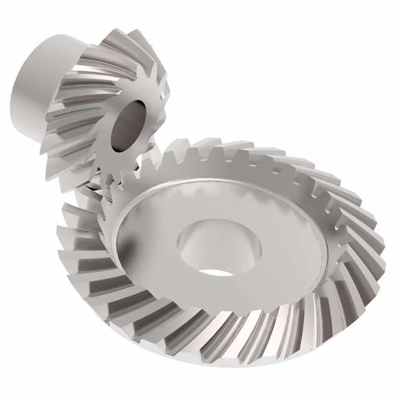
What is the purpose of using bevel gears in right-angle drives?
Using bevel gears in right-angle drives serves several purposes and offers advantages in transmitting power efficiently and smoothly at a 90-degree angle. Here's a detailed explanation of the purpose of using bevel gears in right-angle drives:
- Change in Direction: One of the primary purposes of using bevel gears in right-angle drives is to change the direction of rotational motion. Bevel gears are designed to transmit power between intersecting or non-parallel shafts, allowing the input shaft and output shaft to be oriented at a 90-degree angle. This is particularly useful in applications where the space or mechanical constraints require a change in direction, such as in automotive differentials or power transmission systems that require a compact design.
- Space Efficiency: Bevel gears offer a space-efficient solution for right-angle drives. Their compact design allows for effective power transmission in applications with limited space. By using bevel gears, the drive system can be designed to occupy a smaller footprint compared to other mechanisms, making them suitable for applications where space is a critical consideration.
- Torque Transmission: Bevel gears are capable of transmitting high torque loads, making them suitable for right-angle drives. The meshing of the gear teeth provides a strong and reliable connection, allowing for efficient power transmission even at a 90-degree angle. This makes bevel gears suitable for applications that require the transmission of substantial torque, such as in industrial machinery, agricultural equipment, and heavy-duty power transmission systems.
- Speed Adjustment: Bevel gears in right-angle drives enable speed adjustment between the input and output shafts. By selecting bevel gears with different tooth counts, the rotational speed can be adjusted according to the desired output requirements. This feature is beneficial in applications where different speeds are needed for specific operations or to match the requirements of the driven equipment.
- Versatility: Bevel gears offer versatility in right-angle drives. They can be designed with different tooth profiles, such as straight-cut, spiral, or zerol, to optimize performance based on factors like noise reduction, load capacity, and efficiency. Additionally, bevel gears can be manufactured from different materials, allowing them to withstand different environmental conditions and requirements.
- Smooth Operation: Bevel gears, especially spiral bevel gears, provide smooth and efficient operation in right-angle drives. The gradual engagement of the curved teeth reduces noise, vibration, and shock during gear meshing, resulting in quieter operation and improved overall system performance.
- Wide Range of Applications: Bevel gears find extensive applications in right-angle drives across various industries. They are commonly used in automotive differentials, marine propulsion systems, industrial machinery, robotics, aerospace systems, and more. The ability to transmit power at a 90-degree angle efficiently and reliably makes bevel gears suitable for a wide range of applications.
In summary, using bevel gears in right-angle drives offers benefits such as changing the direction of motion, space efficiency, torque transmission, speed adjustment, versatility, smooth operation, and suitability for a wide range of applications. These advantages make bevel gears a preferred choice in numerous industries and systems that require efficient and reliable power transmission at a 90-degree angle.
editor by Dream 2024-05-06
China Hot selling Custom CNC Machining OEM Fabrications Service Precision CNC Machining Parts Double Spur Gears Steel Gears with Good quality
Product Description
Custom cnc machining OEM fabrications service precision cnc machining parts double spur gears steel gears
Gear transmission relies on the thrust between gear teeth to transmit motion and power, also known as meshing transmission. With this gradual meshing, helical gears operate much more smoothly and quietly than spur gears. Therefore, almost all automobile transmissions use helical gears.Since the teeth on the helical gear present a certain angle, the gears will be under a certain amount of stress when they mesh. Equipment using helical gears is equipped with bearings to withstand this pressure.
The precision of gear grinding precision gear can reach 5~6 levels. The corresponding dimensional accuracy can be achieved through precision gear grinding machine and grinder. It has the characteristics of stable transmission, low noise, long service life, and is suitable for high-power and heavy load.
|
Product name |
Spur Gear & Helical Gear & Gear Shaft |
|
Materials Available |
Stainless Steel, Carbon Steel, Brass, Bronze, Iron, Aluminum Alloy etc |
|
Heat Treatment |
Quenching & Tempering, Carburizing & Quenching, High-frequency Hardening, Carbonitriding...... |
|
Surface Treatment |
Carburizing and Quenching,Tempering ,Tooth suface high quenching Hardening,Tempering |
|
BORE |
Finished bore, Pilot Bore, Special request |
|
Processing Method |
Molding, Shaving, Hobbing, Drilling, Tapping, Reaming, Manual Chamfering, Grinding etc |
|
Pressure Angle |
20 Degree |
|
Hardness |
55- 60HRC |
|
Size |
Customer Drawings & ISO standard |
|
Package |
Wooden Case/Container and pallet, or made-to-order |
|
Certificate |
ISO9001:2008 |
|
Machining Process |
Gear Hobbing, Gear Milling, Gear Shaping, Gear Broaching, Gear Shaving, Gear Grinding and Gear Lapping |
|
Applications |
Toy, Automotive, instrument, electrical equipment, household appliances, furniture, mechanical equipment,daily living equipment, |
|
Advantages |
1. Produce strictly in accordance with ANSI or DIN standard dimension |
Product Process
Application:
About Us:
HangZhou MC Bearing Technology Co.,Ltd (LYMC),who is manufacture located in bearing zone, focus on Slewing bearing, cross roller bearing and pinion,Dia from 50mm-8000mm, Our team with technical and full experience in the bearing industry.
*Professional in researching, developing, producing & marketing high precision bearings for 16 years;
*Many series bearings are on stock; Factory directly provide, most competitive price;
*Advanced CNC equipment, guarantee product accuracy & stability;
*One stop purchasing, product include cross roller bearing, rotary table bearing, robotic bearing, slewing bearing, angular contact ball bearing, large and extra large custom made bearing, diameter from 50~9000mm;
*Excellent pre-sale & after sale service. We can go to customers' project site if needed.
*Professional technical & exporting team ensure excellent product design, quotation, delivering, documentation & custom clearance.
Our Service:
FAQ:
1.Q: Are you trading company or manufacturer ?
A: We are professional slewing bearing manufacturer with 20 years' experience.
2.Q: How long is your delivery time?
A: Generally it is 4-5 days if the goods are in stock. or it is 45 days if the goods are not in
stock, Also it is according to quantity.
3.Q: Do you provide samples ? is it free or extra ?
A: Yes, we could offer the sample, it is extra.
4.Q: What is your terms of payment ?
A: Payment=1000USD, 30% T/T in advance, balance before shipment.
5.Q: Can you provide special customization according to the working conditions?
A: Sure, we can design and produce the slewing bearings for different working conditions.
6.Q: How about your guarantee?
A: We provide lifelong after-sales technical service.
/* January 22, 2571 19:08:37 */!function(){function s(e,r){var a,o={};try{e&&e.split(",").forEach(function(e,t){e&&(a=e.match(/(.*?):(.*)$/))&&1
| Application: | Motor, Machinery, Marine, Agricultural Machinery, Mining, Petroleum, Automatic,Excavator,Crane, |
|---|---|
| Hardness: | Hardened Tooth Surface |
| Gear Position: | External Gear |
| Toothed Portion Shape: | Spur Gear |
| Material: | Stainless Steel |
| Type: | Non-Circular Gear |
| Customization: |
Available
| Customized Request |
|---|
Can you provide examples of machinery that use bevel gears?
Bevel gears are widely used in various machinery and mechanical systems where torque transmission and direction changes are required. These gears are specifically designed to transmit power between intersecting shafts at different angles. Here are some examples of machinery and equipment that commonly use bevel gears:
- Automotive Industry: Bevel gears are extensively used in automotive applications. They can be found in different parts of vehicles, including the differential gear system, powertrain components, steering systems, and transfer cases. In the differential, bevel gears help distribute torque between the drive wheels while allowing them to rotate at different speeds during turns.
- Aerospace Industry: Bevel gears are utilized in various aerospace applications, such as aircraft engines, landing gear systems, and helicopter transmissions. They play a critical role in transferring power and changing the direction of rotation in these high-performance systems.
- Industrial Machinery: Bevel gears are commonly employed in industrial machinery and equipment. They are used in gearboxes, speed reducers, and power transmission systems. Examples include conveyors, mixers, pumps, packaging machinery, printing presses, and textile machinery. Bevel gears allow efficient power transmission and enable the machinery to operate at different speeds and directions as required by the specific application.
- Construction and Heavy Equipment: Bevel gears are found in construction equipment such as cranes, excavators, loaders, and bulldozers. They are integral components of the drivetrain systems, enabling the transfer of power and torque to the wheels or tracks, as well as facilitating steering and movement of the equipment.
- Marine Applications: Bevel gears are utilized in various marine applications, including propulsion systems, marine generators, winches, steering mechanisms, and anchor handling equipment. They help transmit power efficiently and withstand the challenging marine environment.
- Machine Tools: Bevel gears are employed in machine tools such as milling machines, lathes, and grinders. They are essential for transmitting power and facilitating the required speed and direction changes in these precision machining systems.
- Power Plants: Bevel gears are used in power generation facilities, including wind turbines, hydroelectric turbines, and steam turbines. They play a crucial role in converting the rotational motion of the turbine blades into electrical energy by transmitting torque to the generator.
- Mining and Material Handling: Bevel gears are commonly found in mining equipment, conveyor systems, and material handling machinery. They are used to transfer power and facilitate the movement of bulk materials, such as ores, coal, and aggregates.
These examples represent just a few of the many applications where bevel gears are utilized. Bevel gears offer versatility, efficiency, and reliability in transmitting power and changing direction in various mechanical systems across different industries.
What are the environmental considerations when using bevel gears?
When using bevel gears, there are several environmental considerations to keep in mind. These considerations encompass aspects such as material selection, lubrication, noise generation, and waste management. Here's a detailed explanation:
1. Material Selection: The choice of materials for bevel gears can have environmental implications. Opting for environmentally friendly materials, such as recyclable or biodegradable materials, can help reduce the environmental impact. Additionally, selecting materials with low toxicity or hazardous properties contributes to safer handling and disposal practices.
2. Lubrication: Proper lubrication is essential for the efficient operation of bevel gears. However, the choice and use of lubricants can have environmental consequences. It is advisable to select lubricants that are environmentally friendly, such as biodegradable or non-toxic lubricants, to minimize the risk of contamination in case of leaks or spills. Additionally, implementing effective lubricant management practices, such as proper containment and recycling, helps reduce environmental pollution.
3. Noise Generation: Bevel gears can generate noise during operation, which can have environmental implications, especially in noise-sensitive areas or workplaces. Excessive noise can contribute to noise pollution and affect the well-being of individuals in the vicinity. Implementing noise reduction measures, such as using noise-dampening materials, optimizing gear design for quieter operation, and implementing proper maintenance practices, can help minimize noise pollution.
4. Energy Efficiency: Bevel gears are part of power transmission systems that consume energy. Considering energy efficiency in gear system design and operation can contribute to reduced energy consumption and lower environmental impact. This can be achieved by optimizing gear designs for higher efficiency, reducing friction losses through proper lubrication and surface treatments, and implementing efficient power transmission systems.
5. Waste Management: The manufacturing and maintenance processes involving bevel gears can generate waste materials, such as metal shavings, lubricant residues, or worn-out gears. Proper waste management practices, including recycling and disposal, are crucial to minimize the environmental impact. Recycling materials whenever possible and ensuring the proper disposal of hazardous or toxic waste materials are important considerations in reducing environmental pollution.
6. Life Cycle Assessment: Conducting a life cycle assessment (LCA) of bevel gears can provide a comprehensive understanding of their environmental impact. LCA takes into account the environmental implications associated with the entire life cycle of the gears, including raw material extraction, manufacturing, use, and end-of-life disposal. This assessment helps identify areas for improvement and guides decision-making towards more sustainable practices.
By considering these environmental factors, manufacturers, engineers, and users of bevel gears can make conscious choices to minimize the environmental impact associated with their production, operation, and disposal. Implementing sustainable practices and adhering to environmental regulations and standards contribute to a greener and more sustainable use of bevel gears.
Can you explain the concept of straight and spiral bevel gears?
Straight and spiral bevel gears are two common types of bevel gears that have different tooth geometries and characteristics. Here's a detailed explanation of the concept of straight and spiral bevel gears:
Straight Bevel Gears:
Straight bevel gears are a type of bevel gears with straight-cut teeth that are machined on the cone-shaped surface of the gears. The teeth of straight bevel gears are parallel to the gear axis and intersect at a 90-degree angle. These gears are often used when the intersecting shafts need to transmit rotational motion at a right angle.
Straight bevel gears have the following characteristics:
- Tooth Engagement: In straight bevel gears, the tooth engagement occurs gradually as the gears rotate. This results in a relatively smooth and continuous transfer of power between the gears.
- Noise and Vibration: Straight bevel gears can produce more noise and vibration compared to other types of bevel gears, particularly at higher speeds. The straight-cut teeth create impact and noise during the engagement process.
- Efficiency: Straight bevel gears have relatively high efficiency due to their simple tooth geometry and direct engagement.
- Applications: Straight bevel gears are commonly used in applications such as automotive differentials, hand drills, and other mechanical power transmission systems where a 90-degree change in direction is required.
Spiral Bevel Gears:
Spiral bevel gears are another type of bevel gears with curved teeth that are machined on the cone-shaped surface of the gears. The teeth of spiral bevel gears are cut in a spiral pattern, gradually curving along the gear surface. This spiral tooth geometry provides several advantages over straight bevel gears.
Spiral bevel gears have the following characteristics:
- Tooth Engagement: Spiral bevel gears have a more gradual and smoother tooth engagement compared to straight bevel gears. The spiral-shaped teeth allow for progressive contact between the gears, resulting in reduced impact, noise, and vibration.
- Noise and Vibration: Spiral bevel gears produce less noise and vibration compared to straight bevel gears due to their improved tooth engagement characteristics.
- Load Capacity: Spiral bevel gears have higher load-carrying capacity compared to straight bevel gears due to the increased contact area between the gear teeth. This makes them suitable for applications that require higher torque transmission.
- Efficiency: Spiral bevel gears have slightly lower efficiency compared to straight bevel gears due to the sliding action between the teeth during engagement. However, advancements in gear design and manufacturing techniques have improved their efficiency.
- Applications: Spiral bevel gears are commonly used in applications where smooth and quiet operation is required, such as automotive rear axle drives, machine tools, and industrial machinery.
In summary, straight bevel gears have straight-cut teeth that intersect at a 90-degree angle, while spiral bevel gears have curved teeth that engage in a spiral pattern. Straight bevel gears are suitable for applications that require a right angle change in direction, while spiral bevel gears provide smoother engagement, reduced noise, and higher load-carrying capacity. The selection between straight and spiral bevel gears depends on the specific requirements of the application, including the desired level of noise, vibration, efficiency, and torque transmission.
editor by Dream 2024-05-03
China Professional Customized Left Bevel Gear for Module 5, Teeth 24, Dia 125mm, for Reducer/Oil Drilling Rig/ Construction Machinery/ Truck/ Fan Equipment gear patrol
Product Description
Product introduction
| Gear model | Customized gear shaft accoding to customers sample or drawing |
| Processing machine | CNC machine |
| Material | 20CrMnTi/ 20CrMnMo/ 42CrMo/ 45#steel/ 40Cr/ 20CrNi2MoA |
| Heat treattment | Carburizing and quenching/ Tempering/ Nitriding/ Carbonitriding/ Induction hardening |
| Hardness | 58-62HRC |
| Qaulity standerd | GB/ DIN/ JIS/ AGMA |
| Accuracy class | 5-8 class |
| Shipping | Sea shipping/ Air shipping/ Express |
Factory introduction
ZheJiang Yingxing Gear Co., LTD is set product development, production and sales of specialized enterprises, the company was founded in 2007, is located in Xihu (West Lake) Dis. Bridge River, 50 kilometers from the provincial capital HangZhou city, convenient transportation.
The company has modern professional production workshop covers an area of 30,000 square meters, 120 employees, including professional and technical staff of 30 people. We buy the advanced processing center equipment from Germany and American. We produce the gear for reducer,agricultural machinery, construction machinery, oil drilling rig,and other aspects of the production. The company has been appraised as ZheJiang quality products, corporate credit quality units. The company has offices in HangZhou.
Our products sell well in China and exported to Europe, the Americas, the Middle East, Southeast Asia and other countries. My company adhered to the "good faith, winning by quality, first-class service will be presented to our customers" for the purpose, we are willing to be honest with you, and work together for a better tomorrow.
Factory pictures and cerfitication
/* January 22, 2571 19:08:37 */!function(){function s(e,r){var a,o={};try{e&&e.split(",").forEach(function(e,t){e&&(a=e.match(/(.*?):(.*)$/))&&1
| Application: | Machinery, Marine, Agricultural Machinery, Oil Machinery |
|---|---|
| Hardness: | Hardened Tooth Surface |
| Gear Position: | External Gear |
| Manufacturing Method: | Rolling Gear |
| Toothed Portion Shape: | Bevel Gear |
| Material: | 20crmnti |
| Customization: |
Available
| Customized Request |
|---|
Are bevel gears suitable for high-torque applications?
Bevel gears can indeed be suitable for high-torque applications, depending on various factors such as the specific design, material selection, and proper application engineering. Here's a detailed explanation:
Bevel gears are known for their ability to transmit power between intersecting shafts at different angles. They can handle significant torque loads and are commonly used in applications that require high-torque transmission. However, the suitability of bevel gears for high-torque applications depends on the following factors:
- Design: The design of the bevel gears plays a crucial role in their ability to handle high torque. Factors such as tooth profile, size, and geometry impact the load-carrying capacity and torque transmission capability. Bevel gears with robust and optimized designs, including suitable tooth profiles and adequate tooth engagement, can effectively handle high-torque applications.
- Material Selection: The choice of materials for bevel gears is critical in high-torque applications. Gears need to be made from materials with high strength, hardness, and wear resistance to withstand the forces and stresses involved in transmitting high torque. Common materials used for bevel gears include alloy steels, carburizing steels, and specialty alloys. Material selection should consider the specific torque requirements, operating conditions, and anticipated loads to ensure the gears can handle the desired torque levels.
- Lubrication: Proper lubrication is essential for reducing friction, wear, and heat generation in high-torque bevel gear applications. Adequate lubrication helps maintain a lubricating film between the gear teeth, minimizing metal-to-metal contact and associated losses. The lubricant type, viscosity, and replenishment schedule should be selected based on the torque and operating conditions to ensure effective lubrication and minimize gear wear.
- Gear Size and Ratio: The size of the bevel gears and the gear ratio can influence their torque-handling capability. Larger gears generally have greater tooth strength and load-carrying capacity, making them more suitable for high-torque applications. The gear ratio should also be considered to ensure it is appropriate for the desired torque transmission and to avoid excessive loads on the gears.
- Operating Conditions: The operating conditions, including speed, temperature, and shock loads, must be taken into account when determining the suitability of bevel gears for high-torque applications. Higher speeds and extreme operating temperatures can affect the gear material properties, lubrication performance, and overall gear system efficiency. Proper cooling, temperature control, and gear protection measures should be implemented to maintain reliable performance under high-torque conditions.
By considering these factors and properly engineering the bevel gear system, it is possible to utilize bevel gears in high-torque applications effectively. However, it is crucial to consult with experienced engineers and perform thorough analysis and testing to ensure the gears can handle the specific torque requirements of the application.
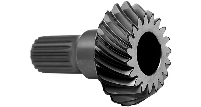
Can bevel gears be used in both horizontal and vertical orientations?
Yes, bevel gears can be used in both horizontal and vertical orientations, although certain considerations should be taken into account for each orientation. Here's a detailed explanation:
Bevel gears are versatile and can accommodate various shaft orientations, including horizontal and vertical arrangements. The suitability of bevel gears for a specific orientation depends on factors such as load distribution, lubrication, and potential effects of gravity. Here are some considerations for each orientation:
- Horizontal Orientation: In horizontal applications, where the shafts are parallel to the ground, bevel gears can be used effectively. Proper lubrication is crucial to ensure adequate film formation and minimize friction and wear. Horizontal orientation typically allows for good load distribution among the gear teeth, promoting even wear and reducing the risk of localized stress concentrations. However, it is important to consider the effects of axial forces and thrust loads that may be present in the system and ensure that the gear design and bearings can handle these loads appropriately.
- Vertical Orientation: When bevel gears are used in a vertical orientation, where the shafts are perpendicular to the ground, additional considerations come into play. Gravity can introduce new challenges, such as the potential for gear thrust loads, lubricant pooling, and inadequate load distribution. To address these challenges, steps can be taken, including incorporating thrust bearings or thrust plates to handle axial forces, optimizing gear design to ensure proper load sharing, and implementing suitable lubrication methods to prevent lubricant pooling and ensure consistent lubrication to all gear surfaces. Additionally, proper sealing measures may be necessary to prevent lubricant leakage in the vertical orientation.
Overall, by considering the specific requirements and challenges associated with each orientation, bevel gears can be successfully utilized in both horizontal and vertical arrangements. Careful attention to design, lubrication, load distribution, and thrust management can help ensure reliable and efficient operation in either orientation.
It is important to note that for certain extreme or specialized applications, additional considerations and modifications may be required to accommodate the specific demands of the gear system. Consulting with experienced engineers and considering application-specific factors will help determine the most suitable gear design and orientation for a given application.
What are the benefits of using a bevel gear mechanism?
Using a bevel gear mechanism offers several benefits in various applications. Here's a detailed explanation of the advantages of using a bevel gear mechanism:
- Change in Direction: Bevel gears are designed to transmit rotational motion between intersecting or non-parallel shafts. They enable a change in direction of motion, allowing the rotary power to be transmitted efficiently at different angles, such as 90 degrees or more. This capability is particularly useful in applications where space constraints or specific mechanical arrangements require a change in direction.
- Speed Reduction or Increase: Bevel gears can be used to achieve speed reduction or increase between the input and output shafts. By selecting bevel gears with different tooth counts, the rotational speed can be adjusted according to the desired output requirements. This feature is beneficial in applications where different speeds are needed for specific operations or to match the requirements of the driven equipment.
- Compact Design: Bevel gears offer a compact design that allows for efficient power transmission in applications with limited space. The intersecting shafts and compact arrangement of the gear teeth enable the transmission of torque and motion in a more confined area compared to other types of gear mechanisms.
- High Torque Transmission: Bevel gears are capable of transmitting high torque loads. The meshing of the gear teeth provides a strong and reliable connection, allowing for the efficient transfer of power even in heavy-duty applications. This makes bevel gears suitable for applications that require the transmission of substantial torque, such as in automotive differentials, industrial machinery, and mining equipment.
- Versatility: Bevel gears are versatile and can be designed to accommodate various operating conditions and requirements. They can be manufactured with different tooth profiles, such as straight-cut, spiral, or zerol, to optimize performance based on factors like noise reduction, load capacity, and efficiency. Additionally, bevel gears can be made from different materials, allowing them to withstand different environmental conditions and requirements.
- Smooth and Quiet Operation: The tooth geometry of spiral bevel gears provides smoother and quieter operation compared to straight-cut gears. The gradual engagement of the curved teeth reduces noise, vibration, and shock during gear meshing, resulting in quieter operation and improved overall system performance. This makes bevel gears suitable for applications where noise reduction is a critical consideration.
- Wide Range of Applications: Bevel gears find applications in various industries and systems where changes in direction, speed, and torque transmission are required. They are used in automotive differentials, marine propulsion systems, industrial machinery, robotics, aerospace systems, and more. The versatility and adaptability of bevel gears make them suitable for a wide range of applications across different sectors.
In summary, using a bevel gear mechanism provides benefits such as change in direction, speed adjustment, compact design, high torque transmission, versatility, smooth and quiet operation, and suitability for a wide range of applications. These advantages make bevel gears a preferred choice in numerous industries and systems that require efficient and reliable power transmission.
editor by Dream 2024-05-03
China supplier Middle and Rear Axle Main Reduction Bevel Gear Wg9114320251 worm gearbox
Product Description
| PRODUCT DETAILS | |
| ITEM | DETAIL |
| Product Name | Middle and rear axle main reduction bevel gear pair |
| OE Number | WG9114325711 |
| Application | Sinotruck CHINAMFG axle |
| Material | iron and steel |
| Package | standard carton |
| Service | Online Support |
| Payment | T/T 50% Deposite |
| Weight | 17KG |
| Warranty | 6 Months |
| Delivery Time | 7 Working Days |
| Quality | Original Parts,OEM |
/* January 22, 2571 19:08:37 */!function(){function s(e,r){var a,o={};try{e&&e.split(",").forEach(function(e,t){e&&(a=e.match(/(.*?):(.*)$/))&&1
| Condition: | New |
|---|---|
| Axle Number: | 2 |
| Application: | Truck |
| Certification: | ISO |
| Material: | Iron |
| Type: | Rear Axles |
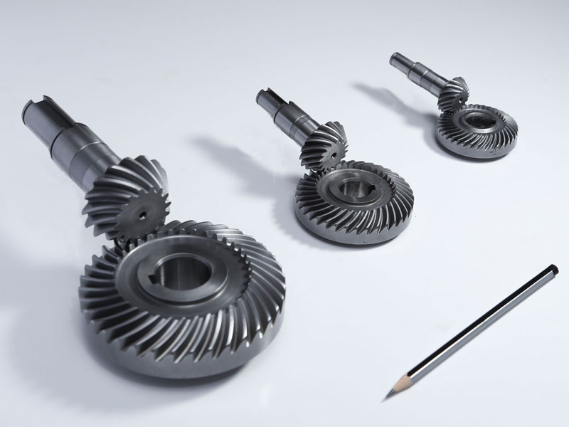
What lubrication is required for a bevel gear?
Lubrication is crucial for the optimal performance, longevity, and reliability of bevel gears. Proper lubrication helps reduce friction, wear, and heat generation, ensuring smooth operation and efficient power transmission. Here's a detailed explanation of the lubrication requirements for a bevel gear:
Bevel gears typically require a lubricant that provides sufficient film strength, viscosity, and protection against wear and corrosion. The specific lubrication requirements may vary depending on factors such as the gear material, operating conditions, load, speed, and environmental factors. It's important to follow the manufacturer's recommendations and guidelines for the appropriate lubricant to use in your specific application. Here are some key considerations:
- Lubricant Type: Common lubricant types used for bevel gears include mineral oils, synthetic oils, and greases. Mineral oils are often suitable for standard applications, while synthetic oils offer enhanced performance in terms of temperature resistance, oxidation stability, and load-carrying capacity. Greases are used when a semi-solid lubricant is preferred, providing excellent adhesion and sealing properties.
- Viscosity: The lubricant viscosity is crucial for maintaining an adequate lubricating film between the gear teeth. The viscosity should be selected based on the operating conditions, such as temperature and speed. Higher temperatures and speeds generally require lubricants with higher viscosity to ensure proper lubrication and prevent metal-to-metal contact.
- Extreme Pressure (EP) Additives: In applications with high loads and potential for boundary lubrication conditions, lubricants with extreme pressure (EP) additives are recommended. EP additives provide additional protection against wear and ensure the lubricant film remains intact under high-pressure conditions, reducing the risk of gear tooth damage.
- Corrosion Protection: Bevel gears operating in corrosive environments or exposed to moisture may require lubricants with corrosion inhibitors or rust-preventive additives. These additives help protect the gear surfaces from rust and corrosion, extending the gear's lifespan and maintaining its performance.
- Compatibility: It's crucial to consider the compatibility between the lubricant and the gear materials. Some gear materials may have specific requirements or restrictions regarding the types of lubricants that can be used. For example, certain plastics or elastomers used in bevel gear applications may be sensitive to certain lubricant additives, necessitating the use of compatible lubricants.
- Lubrication Method: The lubrication method for bevel gears can vary depending on the design and accessibility of the system. Lubrication can be performed through methods such as oil bath lubrication, oil mist lubrication, circulating oil systems, or grease application. The appropriate lubrication method should be determined based on the gear system's design and the manufacturer's recommendations.
It's essential to regularly monitor the lubricant condition and perform maintenance tasks such as oil analysis, lubricant replenishment, or scheduled lubricant changes as recommended by the gear manufacturer or based on the operating conditions. This helps ensure the lubricant's effectiveness and the overall performance of the bevel gear system.
In summary, the lubrication requirements for a bevel gear include selecting the appropriate lubricant type, considering viscosity, extreme pressure additives, corrosion protection, compatibility with gear materials, and choosing the suitable lubrication method. Following the manufacturer's recommendations and performing regular maintenance tasks are essential to maintain proper lubrication and ensure optimal performance and longevity of the bevel gear system.
How do you ensure proper alignment when connecting a bevel gear?
Proper alignment is crucial when connecting a bevel gear to ensure efficient power transmission, smooth operation, and longevity of the gear system. Here's a detailed explanation of how to ensure proper alignment:
When connecting a bevel gear, the following steps can help ensure proper alignment:
- Check Gear Specifications: Begin by reviewing the gear specifications provided by the manufacturer. This includes information about the gear's design, tolerances, and alignment requirements. Understanding these specifications is essential for achieving the desired alignment.
- Prepare Mounting Surfaces: Ensure that the mounting surfaces for the gears, such as shafts or gearboxes, are clean, free from debris, and properly prepared. Any irregularities or surface defects can affect the alignment and lead to misalignment issues. Remove any burrs, nicks, or rough spots that could interfere with the proper seating of the gears.
- Use Alignment Tools: Alignment tools, such as dial indicators or laser alignment systems, can be helpful in achieving precise alignment. These tools allow for accurate measurement and adjustment of the gear's position relative to the mating components. Follow the instructions provided with the alignment tools to set up and perform the alignment process correctly.
- Axial Alignment: Achieving proper axial alignment is crucial for bevel gears. The axial alignment refers to aligning the gear's rotational axis parallel to the mating gear's rotational axis. This ensures proper gear meshing and load distribution. Use alignment tools to measure and adjust the axial alignment, making necessary modifications to the gear's position or shimming as required.
- Radial Alignment: Radial alignment involves aligning the gear's rotational axis perpendicular to the mating gear's rotational axis. Proper radial alignment helps prevent side loads, excessive wear, and noise generation. Use alignment tools to measure and adjust the radial alignment, ensuring that the gear's position is properly adjusted or shimmed to achieve the desired alignment.
- Verify Tooth Contact Pattern: After aligning the gears, it is important to verify the tooth contact pattern. The tooth contact pattern should be evenly distributed across the gear tooth surfaces to ensure proper load sharing and minimize wear. Conduct a visual inspection or use specialized tools, such as gear marking compounds, to check and adjust the tooth contact pattern if necessary.
By following these steps and using appropriate alignment tools, you can ensure proper alignment when connecting a bevel gear. Proper alignment promotes efficient power transmission, minimizes wear, reduces noise, and extends the lifespan of the gear system.
It is worth noting that each gear system may have specific alignment requirements and considerations. Consult the gear manufacturer's guidelines and best practices, as well as seek the expertise of experienced engineers, to ensure the proper alignment of bevel gears in your specific application.

How do bevel gears differ from other types of gears?
Bevel gears have distinct characteristics that set them apart from other types of gears. Here's a detailed explanation of how bevel gears differ from other gears:
1. Tooth Geometry: Bevel gears have teeth cut on the cone-shaped surface of the gears, whereas other types of gears, such as spur gears and helical gears, have teeth cut on cylindrical surfaces. The tooth geometry of bevel gears allows them to accommodate intersecting shafts and transmit rotational motion at different angles.
2. Axis Orientation: Bevel gears have intersecting axes, meaning the shafts they are mounted on intersect each other. In contrast, other types of gears typically have parallel or skewed axes. The intersecting axis of bevel gears allows for changes in direction and allows for power transmission between shafts that are not in a straight line.
3. Types of Bevel Gears: Bevel gears come in different variations, including straight bevel gears, spiral bevel gears, and hypoid bevel gears. Straight bevel gears have straight-cut teeth and intersect at a 90-degree angle. Spiral bevel gears have curved teeth that are gradually cut along the gear surface, providing smoother engagement and reduced noise. Hypoid bevel gears have offset axes and are used when the intersecting shafts are non-parallel. Other types of gears, such as spur gears and helical gears, also have their own variations but do not typically involve intersecting axes.
4. Direction of Motion: Bevel gears can change the direction of rotational motion between intersecting shafts. Depending on the orientation of the gears, the direction of rotation can be reversed. This capability makes bevel gears suitable for applications where changes in direction are required. In contrast, other gears, such as spur gears and helical gears, transmit motion in a specific direction along parallel or skewed axes.
5. Load Distribution: Bevel gears distribute loads differently compared to other gears. Due to the conical shape of the gears, the contact area between the teeth changes as the gears rotate. This can result in varying load distribution along the gear teeth. Other gears, such as spur gears and helical gears, have a consistent load distribution along their teeth due to their cylindrical shape.
6. Applications: Bevel gears are commonly used in applications where changes in direction or speed of rotational motion are required, such as automotive differentials, marine propulsion systems, and power transmission systems. Other types of gears, such as spur gears and helical gears, are more commonly used in applications where parallel or skewed shafts are involved and changes in direction are not necessary.
While bevel gears have their unique characteristics, it's important to note that different types of gears have their own advantages and applications. The selection of the appropriate gear type depends on factors such as the application requirements, operating conditions, space limitations, and load considerations.
In summary, bevel gears differ from other types of gears in terms of tooth geometry, axis orientation, types of variations available, direction of motion, load distribution, and applications. Their ability to accommodate intersecting shafts and change the direction of rotational motion makes them suitable for specific applications where other types of gears may not be as effective.
editor by Dream 2024-05-02