Product Description
Our Services
Product Design Material Selection
Mold Design Mold Making
Bulk Production Logo Printing
Surface Treatment Assembling
Packaging Door to Door Delivery
| Material | Nylon ,mc nylon, POM,ABS,PU,PP,PE,PTFE,UHMWPE,HDPE,LDPE, PVC,etc. |
| Color | Black, white, red, green, transparent or any color according to Pantone code |
| Size | As per customer's requirements |
| Technology | Injection molding, CNC machining, Extrusion |
| Surface Treatment | Powder coating, Zinc coating, Galvanization, Electro-deposition coating, Chrome/zinc/nickel plating, Polishing, Silkscreen, Black oxide |
| Application | Automotive, ATV, Mechanical equipment, Construction, Home appliance, Aviation, Office facilities, Agriculture, etc. |
| Shippment | We have longterm cooperation with internation shipping agent and express company, so that shipping safty and arriving time are secured |
Detail Image
Why Choose Us
Our Machine
Product Range
Contact Us /* January 22, 2571 19:08:37 */!function(){function s(e,r){var a,o={};try{e&&e.split(",").forEach(function(e,t){e&&(a=e.match(/(.*?):(.*)$/))&&1
| Application: | Motor, Electric Cars, Machinery, Toy, Car |
|---|---|
| Hardness: | Hardened Tooth Surface |
| Gear Position: | External Gear |
| Manufacturing Method: | Cast Gear |
| Toothed Portion Shape: | Spur Gear |
| Material: | Plastic |
| Samples: |
US$ 0/Piece
1 Piece(Min.Order) | |
|---|
| Customization: |
Available
| Customized Request |
|---|
Are bevel gears suitable for high-torque applications?
Bevel gears can indeed be suitable for high-torque applications, depending on various factors such as the specific design, material selection, and proper application engineering. Here's a detailed explanation:
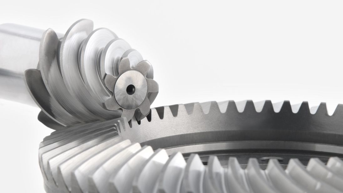
Bevel gears are known for their ability to transmit power between intersecting shafts at different angles. They can handle significant torque loads and are commonly used in applications that require high-torque transmission. However, the suitability of bevel gears for high-torque applications depends on the following factors:
- Design: The design of the bevel gears plays a crucial role in their ability to handle high torque. Factors such as tooth profile, size, and geometry impact the load-carrying capacity and torque transmission capability. Bevel gears with robust and optimized designs, including suitable tooth profiles and adequate tooth engagement, can effectively handle high-torque applications.
- Material Selection: The choice of materials for bevel gears is critical in high-torque applications. Gears need to be made from materials with high strength, hardness, and wear resistance to withstand the forces and stresses involved in transmitting high torque. Common materials used for bevel gears include alloy steels, carburizing steels, and specialty alloys. Material selection should consider the specific torque requirements, operating conditions, and anticipated loads to ensure the gears can handle the desired torque levels.
- Lubrication: Proper lubrication is essential for reducing friction, wear, and heat generation in high-torque bevel gear applications. Adequate lubrication helps maintain a lubricating film between the gear teeth, minimizing metal-to-metal contact and associated losses. The lubricant type, viscosity, and replenishment schedule should be selected based on the torque and operating conditions to ensure effective lubrication and minimize gear wear.
- Gear Size and Ratio: The size of the bevel gears and the gear ratio can influence their torque-handling capability. Larger gears generally have greater tooth strength and load-carrying capacity, making them more suitable for high-torque applications. The gear ratio should also be considered to ensure it is appropriate for the desired torque transmission and to avoid excessive loads on the gears.
- Operating Conditions: The operating conditions, including speed, temperature, and shock loads, must be taken into account when determining the suitability of bevel gears for high-torque applications. Higher speeds and extreme operating temperatures can affect the gear material properties, lubrication performance, and overall gear system efficiency. Proper cooling, temperature control, and gear protection measures should be implemented to maintain reliable performance under high-torque conditions.
By considering these factors and properly engineering the bevel gear system, it is possible to utilize bevel gears in high-torque applications effectively. However, it is crucial to consult with experienced engineers and perform thorough analysis and testing to ensure the gears can handle the specific torque requirements of the application.
How do you address noise and vibration issues in a bevel gear system?
Noise and vibration issues in a bevel gear system can be disruptive, affect performance, and indicate potential problems. Addressing these issues involves identifying the root causes and implementing appropriate solutions. Here's a detailed explanation:
When dealing with noise and vibration in a bevel gear system, the following steps can help address the issues:
- Analyze the System: Begin by analyzing the system to identify the specific sources of noise and vibration. This may involve conducting inspections, measurements, and tests to pinpoint the areas and components contributing to the problem. Common sources of noise and vibration in a bevel gear system include gear misalignment, improper meshing, inadequate lubrication, worn gears, and resonance effects.
- Check Gear Alignment: Proper gear alignment is crucial for minimizing noise and vibration. Misalignment can cause uneven loading, excessive wear, and increased noise. Ensure that the bevel gears are correctly aligned both axially and radially. This can involve adjusting the mounting position, shimming, or realigning the gears to achieve the specified alignment tolerances.
- Optimize Gear Meshing: Proper gear meshing is essential for reducing noise and vibration. Ensure that the gear teeth profiles, sizes, and surface qualities are suitable for the application. Improper tooth contact, such as excessive or insufficient contact, can lead to noise and vibration issues. Adjusting the gear tooth contact pattern, modifying gear profiles, or using anti-backlash gears can help optimize gear meshing and reduce noise and vibration.
- Ensure Adequate Lubrication: Proper lubrication is critical for minimizing friction, wear, and noise in a bevel gear system. Insufficient lubrication or using the wrong lubricant can lead to increased friction and noise generation. Check the lubrication system, ensure the correct lubricant type and viscosity are used, and verify that the gears are adequately lubricated. Regular lubricant analysis and maintenance can help maintain optimal lubrication conditions and reduce noise and vibration.
- Inspect and Replace Worn Gears: Worn or damaged gears can contribute to noise and vibration problems. Regularly inspect the gears for signs of wear, pitting, or tooth damage. If significant wear is detected, consider replacing the worn gears with new ones to restore proper gear meshing and reduce noise. Additionally, ensure that the gear materials are suitable for the application and provide adequate strength and durability.
- Address Resonance Effects: Resonance can amplify noise and vibration in a bevel gear system. Identify any resonant frequencies within the system and take steps to mitigate their effects. This may involve adjusting gear parameters, adding damping materials or structures, or altering the system's natural frequencies to minimize resonance and associated noise and vibration.
Implementing these steps can help address noise and vibration issues in a bevel gear system. However, it is important to note that each system is unique, and the specific solutions may vary depending on the circumstances. Consulting with experts in gear design and vibration analysis can provide valuable insights and ensure effective resolution of noise and vibration problems.

How do you calculate the gear ratio of a bevel gear?
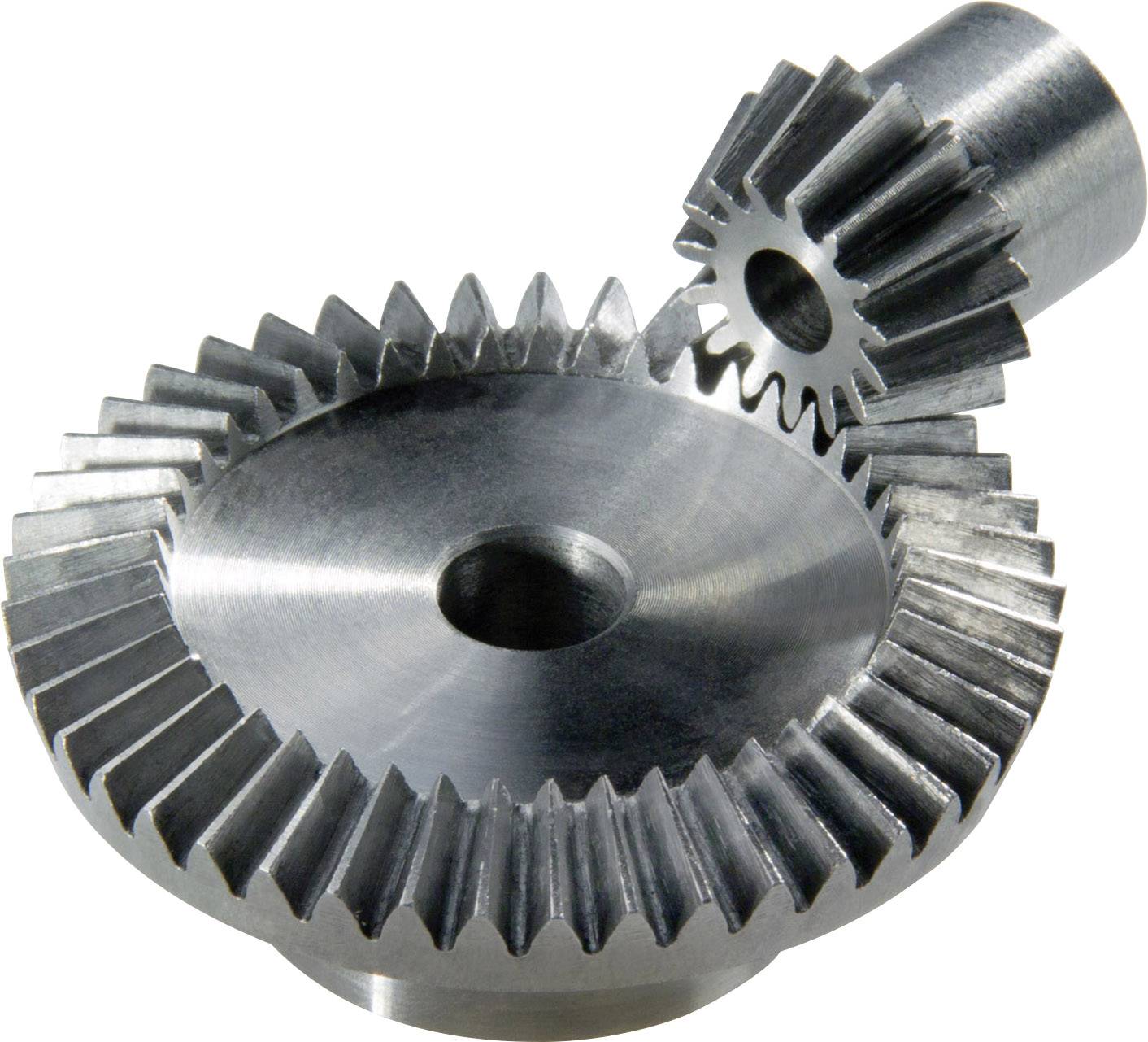
Calculating the gear ratio of a bevel gear involves determining the ratio between the number of teeth on the driving gear (pinion) and the driven gear (crown gear). Here's a detailed explanation of how to calculate the gear ratio of a bevel gear:
The gear ratio is determined by the relationship between the number of teeth on the pinion and the crown gear. The gear ratio is defined as the ratio of the number of teeth on the driven gear (crown gear) to the number of teeth on the driving gear (pinion). It can be calculated using the following formula:
Gear Ratio = Number of Teeth on Crown Gear / Number of Teeth on Pinion Gear
For example, let's consider a bevel gear system with a crown gear that has 40 teeth and a pinion gear with 10 teeth. The gear ratio can be calculated as follows:
Gear Ratio = 40 / 10 = 4
In this example, the gear ratio is 4:1, which means that for every four revolutions of the driving gear (pinion), the driven gear (crown gear) completes one revolution.
It's important to note that the gear ratio can also be expressed as a decimal or a percentage. For the example above, the gear ratio can be expressed as 4 or 400%.
Calculating the gear ratio is essential for understanding the speed relationship and torque transmission between the driving and driven gears in a bevel gear system. The gear ratio determines the relative rotational speed and torque amplification or reduction between the gears.
It's worth mentioning that the gear ratio calculation assumes ideal geometries and does not consider factors such as backlash, efficiency losses, or any other system-specific considerations. In practical applications, it's advisable to consider these factors and consult gear manufacturers or engineers for more accurate calculations and gear selection.
In summary, the gear ratio of a bevel gear is determined by dividing the number of teeth on the crown gear by the number of teeth on the pinion gear. The gear ratio defines the speed and torque relationship between the driving and driven gears in a bevel gear system.


editor by Dream 2024-05-08