Product Description
Product Description
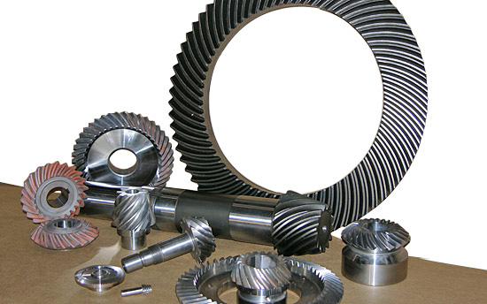
| Material: | 45#Steel,20CrMnTi,40Cr,20CrNiMo,20MnCr5,GCR15SiMn,42CrMo,2Cr13stainless steel,Nylon,Bakelite,Copper,Aluminium.etc |
| Process: | The main process is Gear Hobbing, Gear Shaping and Gear Grinding, Selecting production process according to the different products. |
| Heat Treatmente: | Carburizing and quenching ,High-frequency quenching,Nitriding, Hardening and tempering, Selecting heat treatment according to the different materials. |
| Testing Equipment | Rockwell hardness tester 500RA,
Double mesh instrument HD-200B & 3102, Gear measurement center instrument CNC3906T other High precision detection equipments |
| Certification | 0.1-90 kg |
| Casting Size: | Max linear size: 1200 mm, Max diameter size: 600 mm |
| Machining tolerace: | GB/T19001-2016/ISO9001:2015 |
| Machining surface roughness: | Ra0.8 ~ 6.3 um |
| Material standard: | GB, ASTM, AISI, DIN, BS, JIS, NF, AS, AAR |
| Usage: | Used in printing machine, cleaning machine, medical equipment, garden machine, construction machine, electric car, valve, forklift, transportation equipment and various gear reducers.etc |
| Quality control: | 100% inspection before packing |
| Manufacture Standard | 5-8 Grade ISO1328-1997. |
Company Profile
SIMIS CASTING, established in year of 2004, is a professional foundry, including integrating development and production together, specialized in producing various kinds of investment casting parts, and CHINAMFG parts. These casting parts are widely used in automobile industry, railway vehicle, construction machine, municipal works, pipeline, petrochemical industry, mine, electric utility industry and so on.
SIMIS has 6 affiliated casting workshop and 2 professional CNC machining workshops. There are 500 staffs and 40 engineers now in our company. Its annual production capacity for all types of casting parts is about 3000 tons. Holding over 100 sets of advanced casting parts, machining and test equipments.
It is also equipped with many advanced CNC machining center, CNC turning center, CNC milling machine and CNC lathes. It can do the heat-treatment, electricity polishing, mirror polishing and CNC machining at the request of clients.
Application Field
Testing Ability
| Dimensional | Non-Destructive Tests(N.D.T.) | Chemical & Mechanical |
| Surface Roughness Test | Dye Penetrant | Chemical analysis |
| Microscopic Measurement | Radiography (RT) | Metallography |
| 3D ScHangZhou | Magnetic Particle (MT) | Tensile Strength |
| CMM | Ultra-Sonic (UT) | Yield Strength |
| Impact Test | Hardness Test | Elongation Rate |
| Shrinkage Rate |
Surface Treatment
FAQ
Q1:Are you manufactory or trade company?
A1:We are an enterprise integrating manufacturer and trade for many years already in ZheJiang province, China. And we are AAA grade credit enterprise, and also we have cooperative plants to provide other services such as plating and coating .
Q2: How could I get a free quotation?
A2:Please send us your drawings by Alibaba or email. The file format is PDF / DWG / STP / STEP / IGS and etc. IF there are no drawings, we can make the drawings according to your samples!
Q3:How to control quality?
A3:First, all raw materials are inspected by the quality control department before they are put into storage. Second, during the casting process, 3 times of spectral analysis were performed at the front, middle and back respectively. Third, after the parts are cleaned, perform a first visual inspection to check whether the product has casting defects before sending it to the next process. Fourth, conduct a comprehensive QC inspection of each part before shipment, including chemical composition, mechanical properties and other specific tests. Transactions can be through Alibaba's trade assurance.
Q4:Can we have our Logo or company name to be printed on your products or package?
A4:Sure. Your Logo could be printed on your products by Hot Stamping, Printing, Embossing, UV Coating, Silk-screen Printing or Sticker.
/* January 22, 2571 19:08:37 */!function(){function s(e,r){var a,o={};try{e&&e.split(",").forEach(function(e,t){e&&(a=e.match(/(.*?):(.*)$/))&&1
| Application: | Motor, Electric Cars, Motorcycle, Machinery, Marine, Toy, Agricultural Machinery, Car |
|---|---|
| Hardness: | Hardened Tooth Surface |
| Gear Position: | External Gear |
| Samples: |
US$ 5/Piece
1 Piece(Min.Order) | Order Sample |
|---|
| Customization: |
Available
| Customized Request |
|---|
.shipping-cost-tm .tm-status-off{background: none;padding:0;color: #1470cc}
|
Shipping Cost:
Estimated freight per unit. |
about shipping cost and estimated delivery time. |
|---|
| Payment Method: |
|
|---|---|
|
Initial Payment Full Payment |
| Currency: | US$ |
|---|
| Return&refunds: | You can apply for a refund up to 30 days after receipt of the products. |
|---|

Can you provide examples of machinery that use bevel gears?
Bevel gears are widely used in various machinery and mechanical systems where torque transmission and direction changes are required. These gears are specifically designed to transmit power between intersecting shafts at different angles. Here are some examples of machinery and equipment that commonly use bevel gears:
- Automotive Industry: Bevel gears are extensively used in automotive applications. They can be found in different parts of vehicles, including the differential gear system, powertrain components, steering systems, and transfer cases. In the differential, bevel gears help distribute torque between the drive wheels while allowing them to rotate at different speeds during turns.
- Aerospace Industry: Bevel gears are utilized in various aerospace applications, such as aircraft engines, landing gear systems, and helicopter transmissions. They play a critical role in transferring power and changing the direction of rotation in these high-performance systems.
- Industrial Machinery: Bevel gears are commonly employed in industrial machinery and equipment. They are used in gearboxes, speed reducers, and power transmission systems. Examples include conveyors, mixers, pumps, packaging machinery, printing presses, and textile machinery. Bevel gears allow efficient power transmission and enable the machinery to operate at different speeds and directions as required by the specific application.
- Construction and Heavy Equipment: Bevel gears are found in construction equipment such as cranes, excavators, loaders, and bulldozers. They are integral components of the drivetrain systems, enabling the transfer of power and torque to the wheels or tracks, as well as facilitating steering and movement of the equipment.
- Marine Applications: Bevel gears are utilized in various marine applications, including propulsion systems, marine generators, winches, steering mechanisms, and anchor handling equipment. They help transmit power efficiently and withstand the challenging marine environment.
- Machine Tools: Bevel gears are employed in machine tools such as milling machines, lathes, and grinders. They are essential for transmitting power and facilitating the required speed and direction changes in these precision machining systems.
- Power Plants: Bevel gears are used in power generation facilities, including wind turbines, hydroelectric turbines, and steam turbines. They play a crucial role in converting the rotational motion of the turbine blades into electrical energy by transmitting torque to the generator.
- Mining and Material Handling: Bevel gears are commonly found in mining equipment, conveyor systems, and material handling machinery. They are used to transfer power and facilitate the movement of bulk materials, such as ores, coal, and aggregates.
These examples represent just a few of the many applications where bevel gears are utilized. Bevel gears offer versatility, efficiency, and reliability in transmitting power and changing direction in various mechanical systems across different industries.

How do you ensure proper alignment when connecting a bevel gear?
Proper alignment is crucial when connecting a bevel gear to ensure efficient power transmission, smooth operation, and longevity of the gear system. Here's a detailed explanation of how to ensure proper alignment:
When connecting a bevel gear, the following steps can help ensure proper alignment:
- Check Gear Specifications: Begin by reviewing the gear specifications provided by the manufacturer. This includes information about the gear's design, tolerances, and alignment requirements. Understanding these specifications is essential for achieving the desired alignment.
- Prepare Mounting Surfaces: Ensure that the mounting surfaces for the gears, such as shafts or gearboxes, are clean, free from debris, and properly prepared. Any irregularities or surface defects can affect the alignment and lead to misalignment issues. Remove any burrs, nicks, or rough spots that could interfere with the proper seating of the gears.
- Use Alignment Tools: Alignment tools, such as dial indicators or laser alignment systems, can be helpful in achieving precise alignment. These tools allow for accurate measurement and adjustment of the gear's position relative to the mating components. Follow the instructions provided with the alignment tools to set up and perform the alignment process correctly.
- Axial Alignment: Achieving proper axial alignment is crucial for bevel gears. The axial alignment refers to aligning the gear's rotational axis parallel to the mating gear's rotational axis. This ensures proper gear meshing and load distribution. Use alignment tools to measure and adjust the axial alignment, making necessary modifications to the gear's position or shimming as required.
- Radial Alignment: Radial alignment involves aligning the gear's rotational axis perpendicular to the mating gear's rotational axis. Proper radial alignment helps prevent side loads, excessive wear, and noise generation. Use alignment tools to measure and adjust the radial alignment, ensuring that the gear's position is properly adjusted or shimmed to achieve the desired alignment.
- Verify Tooth Contact Pattern: After aligning the gears, it is important to verify the tooth contact pattern. The tooth contact pattern should be evenly distributed across the gear tooth surfaces to ensure proper load sharing and minimize wear. Conduct a visual inspection or use specialized tools, such as gear marking compounds, to check and adjust the tooth contact pattern if necessary.
By following these steps and using appropriate alignment tools, you can ensure proper alignment when connecting a bevel gear. Proper alignment promotes efficient power transmission, minimizes wear, reduces noise, and extends the lifespan of the gear system.
It is worth noting that each gear system may have specific alignment requirements and considerations. Consult the gear manufacturer's guidelines and best practices, as well as seek the expertise of experienced engineers, to ensure the proper alignment of bevel gears in your specific application.

How do you calculate the gear ratio of a bevel gear?
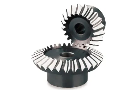
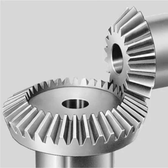
Calculating the gear ratio of a bevel gear involves determining the ratio between the number of teeth on the driving gear (pinion) and the driven gear (crown gear). Here's a detailed explanation of how to calculate the gear ratio of a bevel gear:
The gear ratio is determined by the relationship between the number of teeth on the pinion and the crown gear. The gear ratio is defined as the ratio of the number of teeth on the driven gear (crown gear) to the number of teeth on the driving gear (pinion). It can be calculated using the following formula:
Gear Ratio = Number of Teeth on Crown Gear / Number of Teeth on Pinion Gear
For example, let's consider a bevel gear system with a crown gear that has 40 teeth and a pinion gear with 10 teeth. The gear ratio can be calculated as follows:
Gear Ratio = 40 / 10 = 4
In this example, the gear ratio is 4:1, which means that for every four revolutions of the driving gear (pinion), the driven gear (crown gear) completes one revolution.
It's important to note that the gear ratio can also be expressed as a decimal or a percentage. For the example above, the gear ratio can be expressed as 4 or 400%.
Calculating the gear ratio is essential for understanding the speed relationship and torque transmission between the driving and driven gears in a bevel gear system. The gear ratio determines the relative rotational speed and torque amplification or reduction between the gears.
It's worth mentioning that the gear ratio calculation assumes ideal geometries and does not consider factors such as backlash, efficiency losses, or any other system-specific considerations. In practical applications, it's advisable to consider these factors and consult gear manufacturers or engineers for more accurate calculations and gear selection.
In summary, the gear ratio of a bevel gear is determined by dividing the number of teeth on the crown gear by the number of teeth on the pinion gear. The gear ratio defines the speed and torque relationship between the driving and driven gears in a bevel gear system.


editor by Dream 2024-05-07