Product Description
Our Products Special Features,
1) Our products passed TS16949 ISO-9001: 2000 quality management system verification
2) Material: Steel, copper, brass, aluminum, Titanium
3) Equipment: CNC lathe, CNC milling machine, CNC high-speed engraving machine, Common machines, laser engraving machines, metal injection machine
4) Precision machining capability:
5) Advanced workmanship, fitting tool, fixture, cutting tool
6) Parts can be supplied according to customers' drawings or samples.
7) 2D/3D drawings or samples are welcome!
8). Best quality, competitive price, shortest delivery time and good service.
| Place of origin: | ZHangZhoug, China |
| Brand Name: | HangZhou Xihu (West Lake) Dis. Powder Metallurgy Co.,Ltd |
| Type: | Powder metallurgy sintering |
| Surface finish | e-coating, electroplating and black oxygen |
| Measuring method | 3D system, High-lubrication, high-density and high-strength |
| Inspection equipment | Torsion test, voltage feedback test, HRC density test, lifting test and salt spray resistant test and more |
| Spare parts type: | Powder metallurgy parts |
| Machinery Test report: | Provided |
| Material: | Iron, stainless steel, copper, Alloy |
| Application: | Automotive parts, power tools, stainless steel, bushings, clutches and so many others |
| Plating: | Customized |
| After-sales Service: | Online support |
| Processing: | Powder Metallurgy, CNC Machining |
| Powder Metallurgy: | High frequency quenching, oil immersion |
| Quality Control: | 100% inspection |
| Application: | Motor, Electric Cars, Motorcycle, Machinery, Marine, Agricultural Machinery, Car |
|---|---|
| Hardness: | Hardened Tooth Surface |
| Gear Position: | Customized Gear |
| Manufacturing Method: | Sintered Gear |
| Toothed Portion Shape: | Customized |
| Material: | Sintered Metal |
| Samples: |
US$ 0.5/Piece
1 Piece(Min.Order) | |
|---|
| Customization: |
Available
| Customized Request |
|---|

How do you prevent backlash and gear play in a bevel gear mechanism?
In a bevel gear mechanism, preventing backlash and gear play is essential for ensuring accurate and efficient power transmission. Backlash refers to the clearance or free movement between the mating teeth of gears, resulting in a brief loss of motion or a dead zone when changing direction. Here are some methods to prevent backlash and minimize gear play in a bevel gear mechanism:
- Precision Manufacturing: High-precision manufacturing processes are crucial for minimizing backlash and gear play in bevel gears. Accurate machining of gear teeth and precise control of tooth dimensions, profiles, and alignment help achieve tight meshing between the gears, reducing the clearance and backlash. Modern manufacturing techniques, such as CNC machining and gear grinding, can ensure the desired level of precision and minimize gear play.
- Proper Gear Design: The design of the bevel gears can influence the amount of backlash and gear play. An optimized gear design, including suitable tooth profiles, pressure angles, and tooth contact patterns, can help distribute the load evenly and minimize the clearance between the mating teeth. By carefully considering gear design parameters, designers can reduce backlash and improve gear meshing characteristics.
- Preload or Pre-Tension: Applying a preload or pre-tension to the bevel gears can help minimize backlash and gear play. This involves applying a slight force or tension to the gears, forcing them to maintain contact and reducing the clearance between the teeth. Preload can be achieved through various methods, such as using spring mechanisms, shimming, or adjusting the mounting position of the gears.
- Backlash Compensation: Backlash compensation methods aim to minimize the effects of backlash and gear play by introducing mechanisms or techniques that compensate for the clearance. One common approach is to use anti-backlash gears, which have special tooth profiles or arrangements that reduce or eliminate clearance between the mating teeth. Another method is to incorporate backlash compensation devices, such as spring-loaded mechanisms or adjustable shims, that actively reduce the backlash during operation.
- Tight Control of Tolerances: Maintaining tight tolerances during the manufacturing and assembly processes is critical for minimizing backlash and gear play. Close control of dimensions, alignment, and clearances ensures proper gear meshing and reduces the possibility of excessive play. Quality control measures, such as inspection, testing, and verification of gear dimensions, can help ensure that the gears meet the specified tolerances.
- Regular Maintenance: Regular maintenance practices, including inspection, lubrication, and adjustment, are essential for preventing and minimizing backlash and gear play over time. Periodic checks for wear, misalignment, and proper lubrication can help identify and rectify any issues that may contribute to increased backlash. Timely maintenance and replacement of worn or damaged gears can help maintain optimal gear meshing and minimize play.
By implementing these methods, it is possible to significantly reduce backlash and gear play in a bevel gear mechanism, resulting in improved accuracy, efficiency, and longevity of the gear system.

How do you ensure proper alignment when connecting a bevel gear?
Proper alignment is crucial when connecting a bevel gear to ensure efficient power transmission, smooth operation, and longevity of the gear system. Here's a detailed explanation of how to ensure proper alignment:
When connecting a bevel gear, the following steps can help ensure proper alignment:
- Check Gear Specifications: Begin by reviewing the gear specifications provided by the manufacturer. This includes information about the gear's design, tolerances, and alignment requirements. Understanding these specifications is essential for achieving the desired alignment.
- Prepare Mounting Surfaces: Ensure that the mounting surfaces for the gears, such as shafts or gearboxes, are clean, free from debris, and properly prepared. Any irregularities or surface defects can affect the alignment and lead to misalignment issues. Remove any burrs, nicks, or rough spots that could interfere with the proper seating of the gears.
- Use Alignment Tools: Alignment tools, such as dial indicators or laser alignment systems, can be helpful in achieving precise alignment. These tools allow for accurate measurement and adjustment of the gear's position relative to the mating components. Follow the instructions provided with the alignment tools to set up and perform the alignment process correctly.
- Axial Alignment: Achieving proper axial alignment is crucial for bevel gears. The axial alignment refers to aligning the gear's rotational axis parallel to the mating gear's rotational axis. This ensures proper gear meshing and load distribution. Use alignment tools to measure and adjust the axial alignment, making necessary modifications to the gear's position or shimming as required.
- Radial Alignment: Radial alignment involves aligning the gear's rotational axis perpendicular to the mating gear's rotational axis. Proper radial alignment helps prevent side loads, excessive wear, and noise generation. Use alignment tools to measure and adjust the radial alignment, ensuring that the gear's position is properly adjusted or shimmed to achieve the desired alignment.
- Verify Tooth Contact Pattern: After aligning the gears, it is important to verify the tooth contact pattern. The tooth contact pattern should be evenly distributed across the gear tooth surfaces to ensure proper load sharing and minimize wear. Conduct a visual inspection or use specialized tools, such as gear marking compounds, to check and adjust the tooth contact pattern if necessary.
By following these steps and using appropriate alignment tools, you can ensure proper alignment when connecting a bevel gear. Proper alignment promotes efficient power transmission, minimizes wear, reduces noise, and extends the lifespan of the gear system.
It is worth noting that each gear system may have specific alignment requirements and considerations. Consult the gear manufacturer's guidelines and best practices, as well as seek the expertise of experienced engineers, to ensure the proper alignment of bevel gears in your specific application.

Can you explain the concept of straight and spiral bevel gears?
Straight and spiral bevel gears are two common types of bevel gears that have different tooth geometries and characteristics. Here's a detailed explanation of the concept of straight and spiral bevel gears:
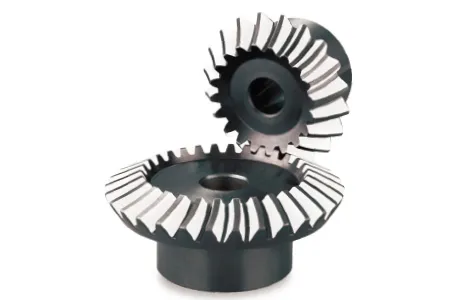
Straight Bevel Gears:
Straight bevel gears are a type of bevel gears with straight-cut teeth that are machined on the cone-shaped surface of the gears. The teeth of straight bevel gears are parallel to the gear axis and intersect at a 90-degree angle. These gears are often used when the intersecting shafts need to transmit rotational motion at a right angle.
Straight bevel gears have the following characteristics:
- Tooth Engagement: In straight bevel gears, the tooth engagement occurs gradually as the gears rotate. This results in a relatively smooth and continuous transfer of power between the gears.
- Noise and Vibration: Straight bevel gears can produce more noise and vibration compared to other types of bevel gears, particularly at higher speeds. The straight-cut teeth create impact and noise during the engagement process.
- Efficiency: Straight bevel gears have relatively high efficiency due to their simple tooth geometry and direct engagement.
- Applications: Straight bevel gears are commonly used in applications such as automotive differentials, hand drills, and other mechanical power transmission systems where a 90-degree change in direction is required.
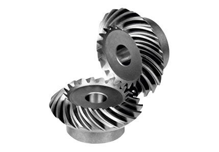
Spiral Bevel Gears:
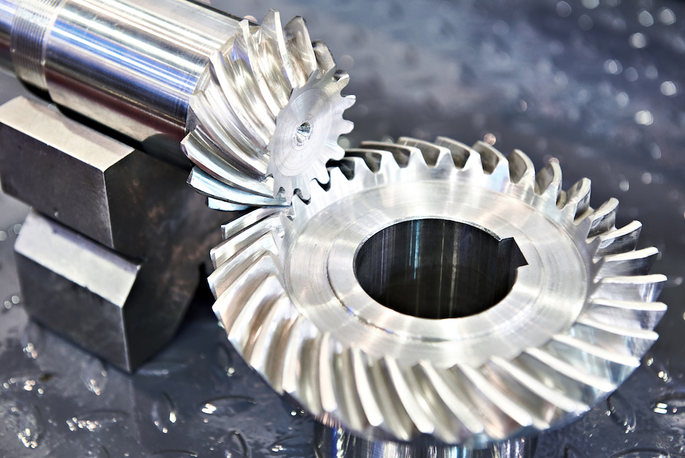
Spiral bevel gears are another type of bevel gears with curved teeth that are machined on the cone-shaped surface of the gears. The teeth of spiral bevel gears are cut in a spiral pattern, gradually curving along the gear surface. This spiral tooth geometry provides several advantages over straight bevel gears.
Spiral bevel gears have the following characteristics:
- Tooth Engagement: Spiral bevel gears have a more gradual and smoother tooth engagement compared to straight bevel gears. The spiral-shaped teeth allow for progressive contact between the gears, resulting in reduced impact, noise, and vibration.
- Noise and Vibration: Spiral bevel gears produce less noise and vibration compared to straight bevel gears due to their improved tooth engagement characteristics.
- Load Capacity: Spiral bevel gears have higher load-carrying capacity compared to straight bevel gears due to the increased contact area between the gear teeth. This makes them suitable for applications that require higher torque transmission.
- Efficiency: Spiral bevel gears have slightly lower efficiency compared to straight bevel gears due to the sliding action between the teeth during engagement. However, advancements in gear design and manufacturing techniques have improved their efficiency.
- Applications: Spiral bevel gears are commonly used in applications where smooth and quiet operation is required, such as automotive rear axle drives, machine tools, and industrial machinery.
In summary, straight bevel gears have straight-cut teeth that intersect at a 90-degree angle, while spiral bevel gears have curved teeth that engage in a spiral pattern. Straight bevel gears are suitable for applications that require a right angle change in direction, while spiral bevel gears provide smoother engagement, reduced noise, and higher load-carrying capacity. The selection between straight and spiral bevel gears depends on the specific requirements of the application, including the desired level of noise, vibration, efficiency, and torque transmission.


editor by CX 2023-10-17